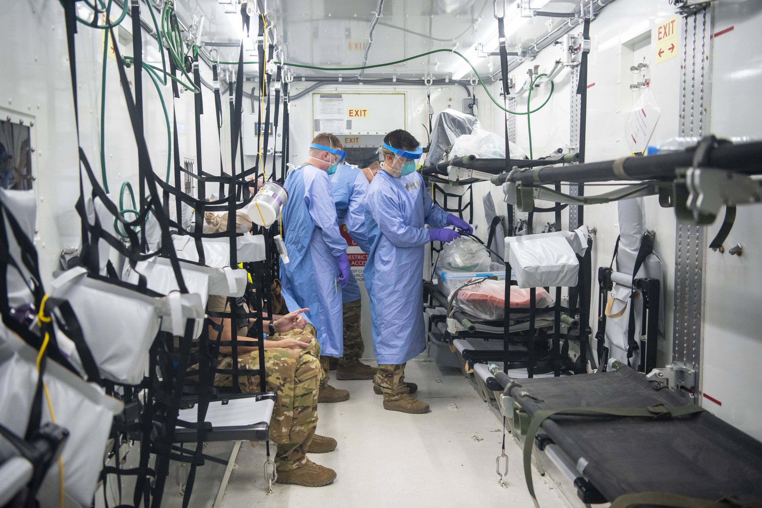
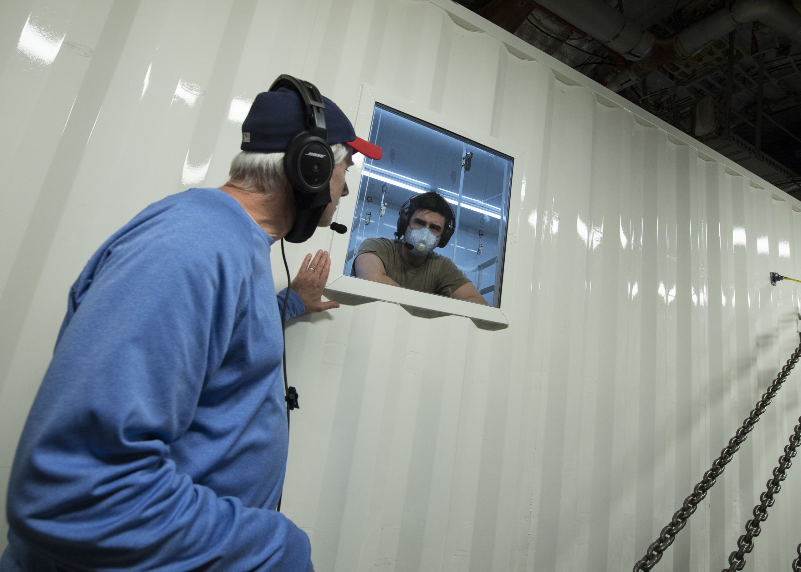
U.S. Air Force personnel of the 379th Expeditionary Aeromedical Evacuation Squadron simulate transporting COVID-19 patients on a static C-130 Hercules aircraft during training on the Negative Pressurized Conex- Lite (NPC-L) at Al Udeid Air Base, Qatar. USAF photo by Senior Airman Ashley Perdue, 07AUG2020.
“This is unlike anything we’ve seen in the Air Force….. ….This is a crazy effort.”-Captain Conner Favo, 28th Test & Evaluation Squadron, a famous last words statement as a similar device was used during Viet Nam (see below)
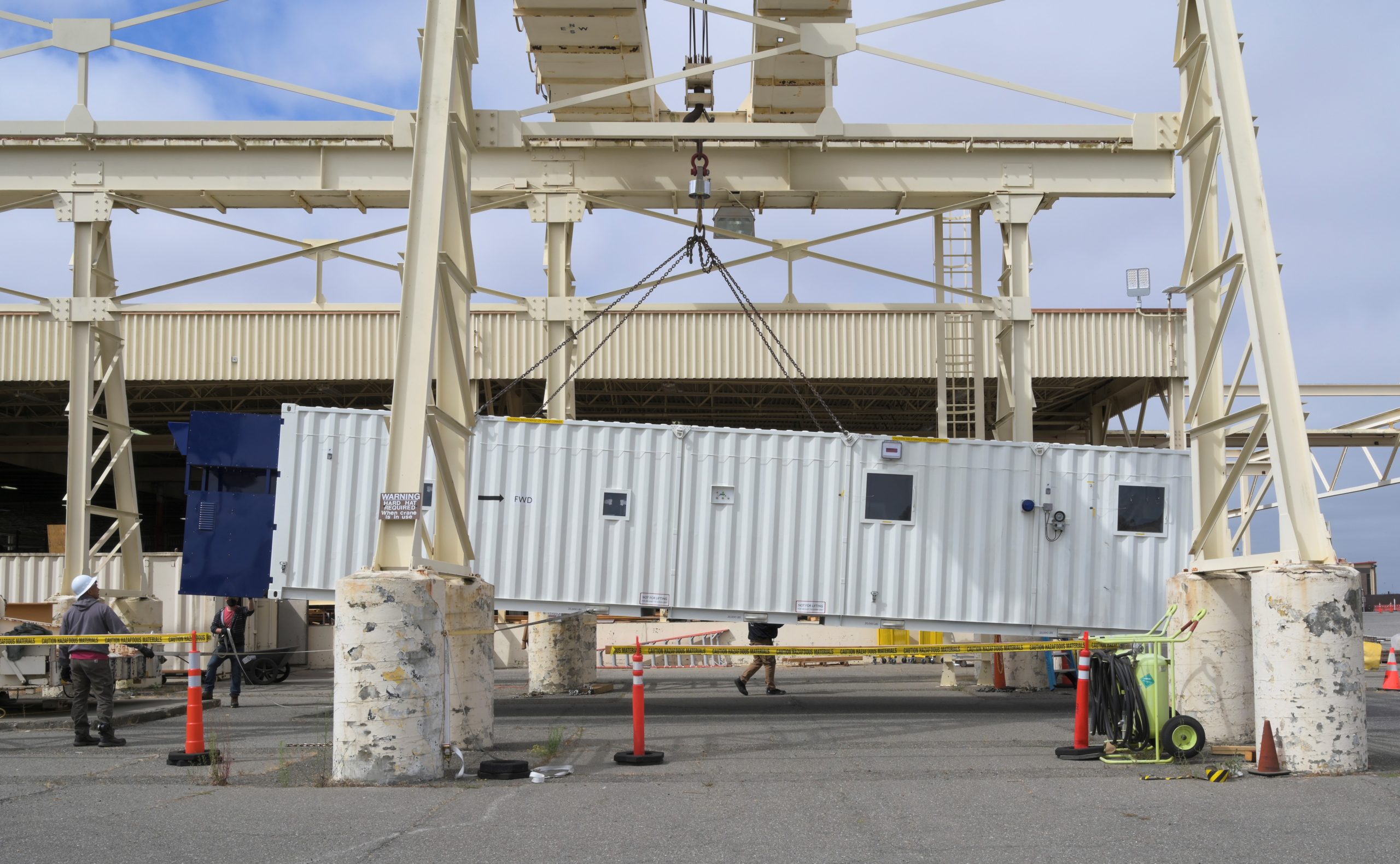
Travis AFB, California. USAF photo by Lan Kim, 05AUG2020.
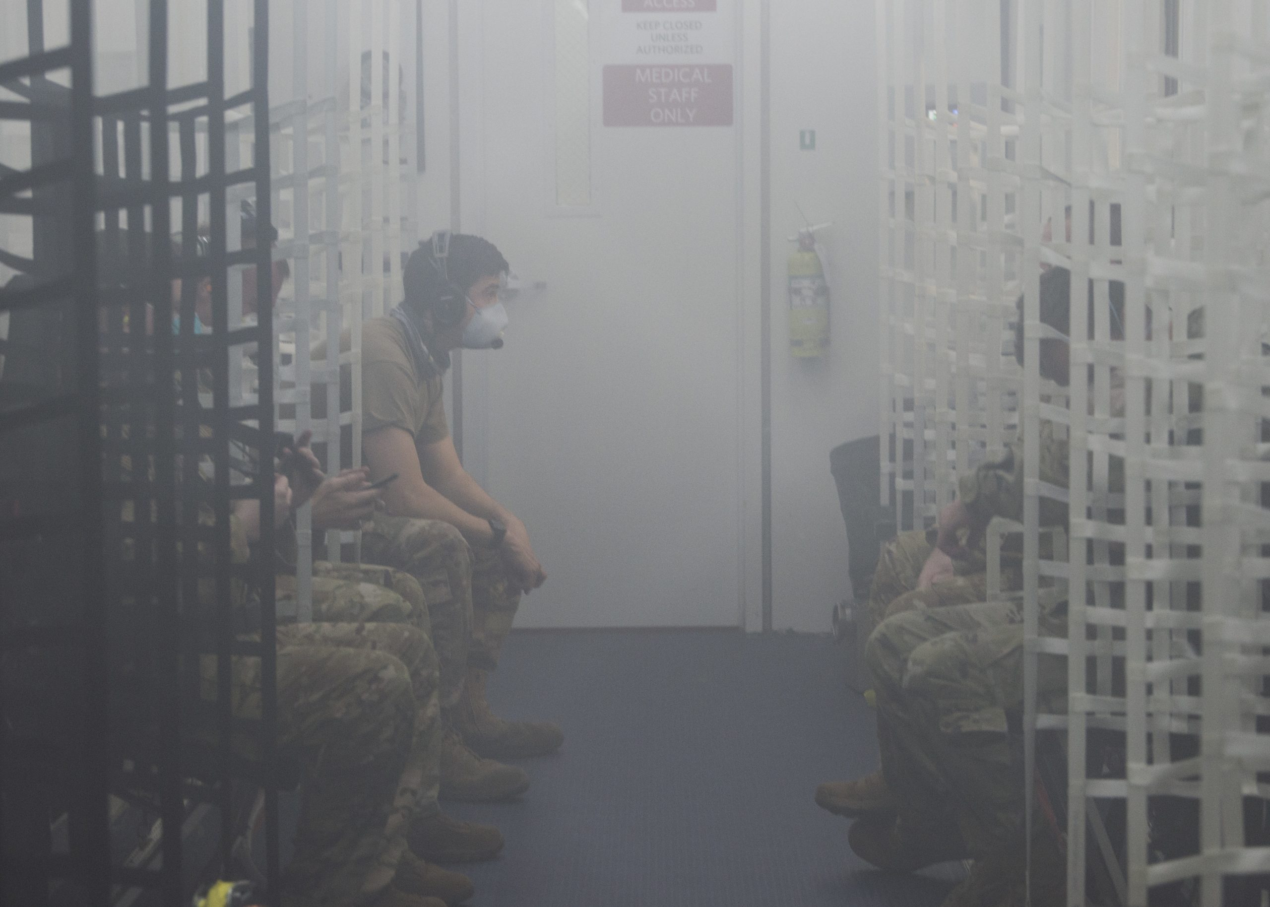
A multi-agency team involving the U.S. Department of Defense, contractors and universities, has been preparing for massive aeromedical evacuation operations of pandemic victims (prior to the Pandemic, some how), and has developed what it calls Negative Pressure Conex (NPC) containers to isolate those future victims in while being flown to military hospitals.
“The team in the 28th TES is no stranger to bio-containment. We provided this support when developing the Transportation Isolation System for the Ebola crisis, and we’re making every effort to ensure our fellow service members have safe transportation during these times.”-Captain Conner Favo, 28th Test & Evaluation Squadron
Video, NPC testing on the ground:

They modified a steel cargo container known as a Conex (most often seen on cargo ships and tractor-trailer rigs) with an air conditioning system to create a negative pressure inside the Conex while being flown on a C-17 Globemaster-3 or C-5 Galaxy transport aircraft. This is considered important to be able to keep the positive pressurized aircraft and its crew from being contaminated.
NPC testing on Joint Base Charleston, South Carolina. USAF photo by Staff Sergeant Chris Drzazgowski, 01MAY2020.
Video, NPC testing onboard C-17 transport:
NPC testing on Joint Base Charleston, South Carolina. USAF photo by Staff Sergeant Chris Drzazgowski, 01MAY2020.
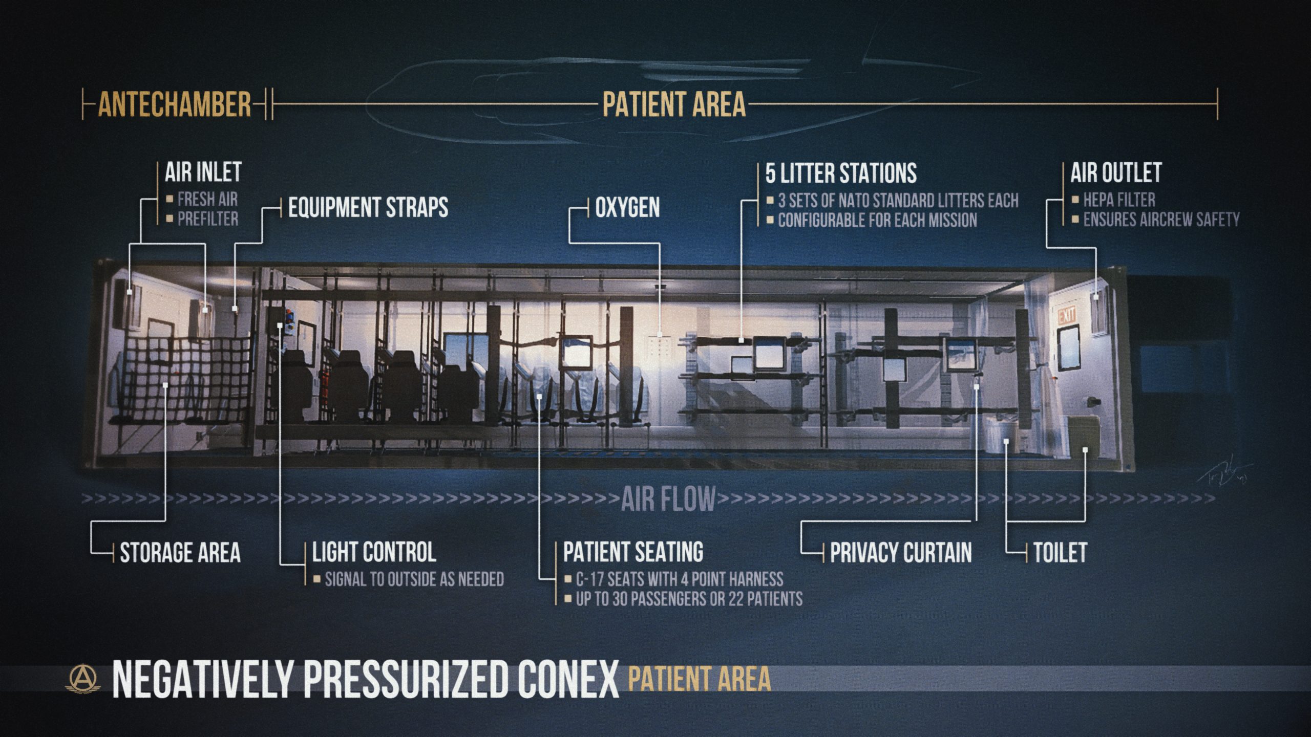
The NPC is designed to transport up to 28 victims and medical personnel.
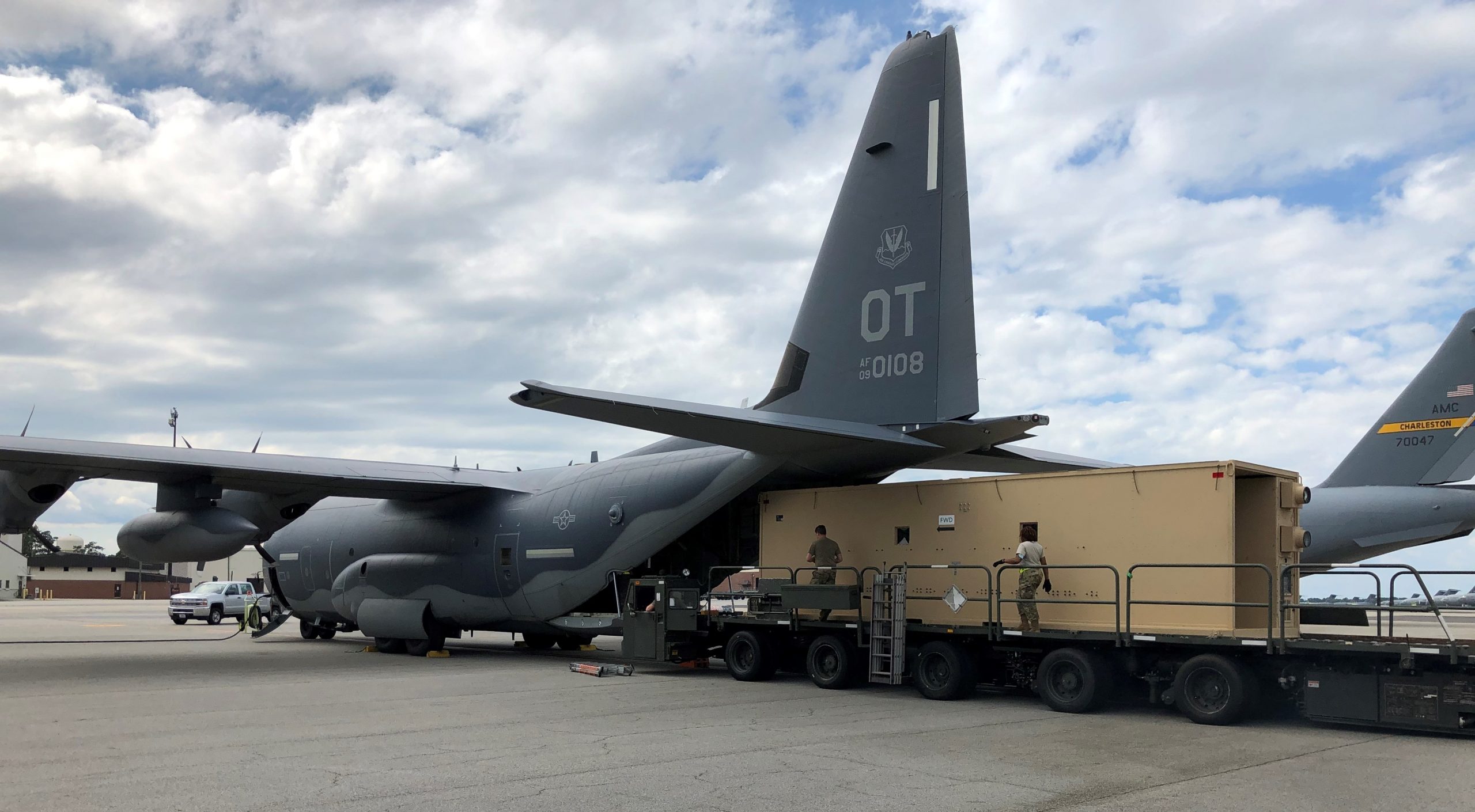
NPC-Lite system loaded inside a C-130 Hercules, on Joint Base Charleston, South Carolina. U.S. Army photo by Brian Feeney, 13JUN2020.
Official USAF video report:
Testing was done in April/May of 2020, by the personnel of 437th Airlift Wing, at Joint Base Charleston, South Carolina. Other U.S. Air Force units involved include the Agile Combat Support Directorate and the CBRN (Chemical, Biological, Radiological, Nuclear) Defense Systems Branch.

U.S. Army Contracting Command slashed a 4-month contracting award process to just 7 days, with delivery of the prototype in only 13 days at an approximate cost of $2-million. The first operational NPCs are expected to go into use by the end of May 2020.
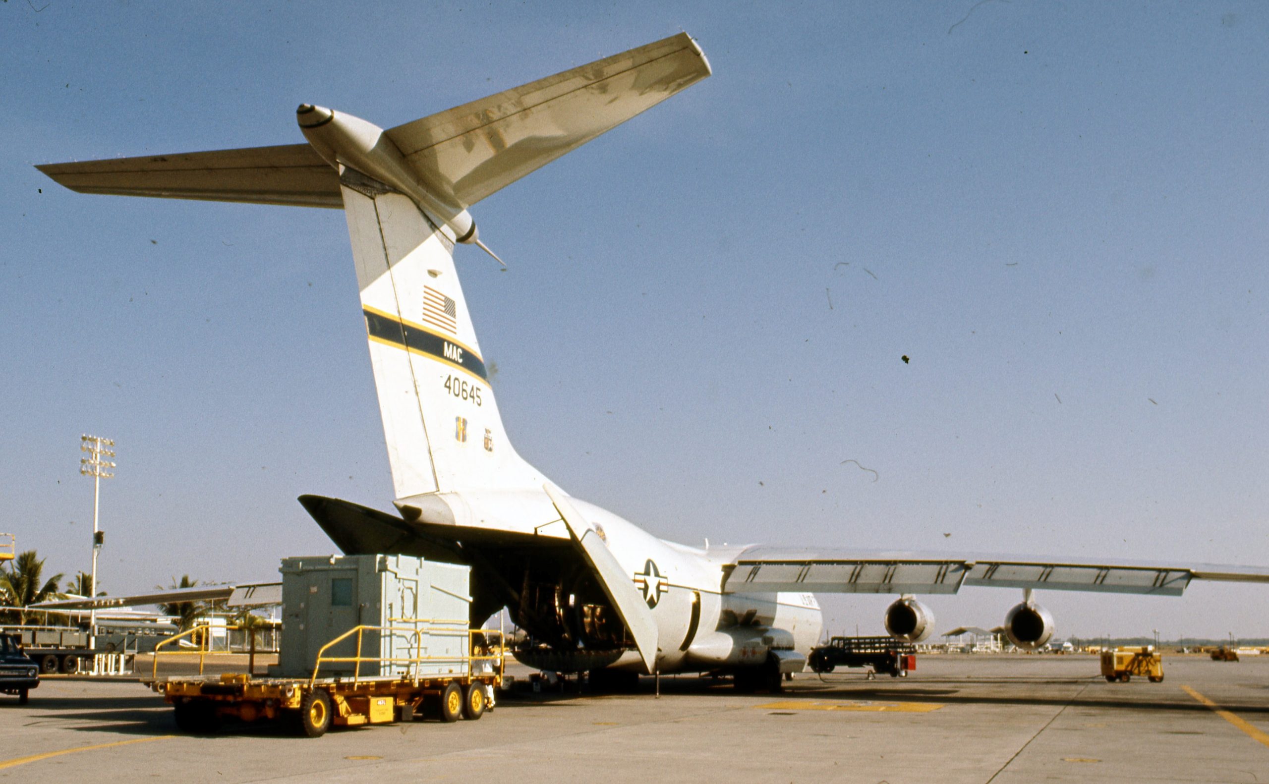
USAF photo sometime between March & April 1973, Clark Air Base, Philippines.
Realize that a lot of tax dollars have been spent on this not so new technology that is being sold as innovative. I say not so new, because back in the early 1970s the USAF used a similar ‘NPC’ on a C-141A Starlifter.
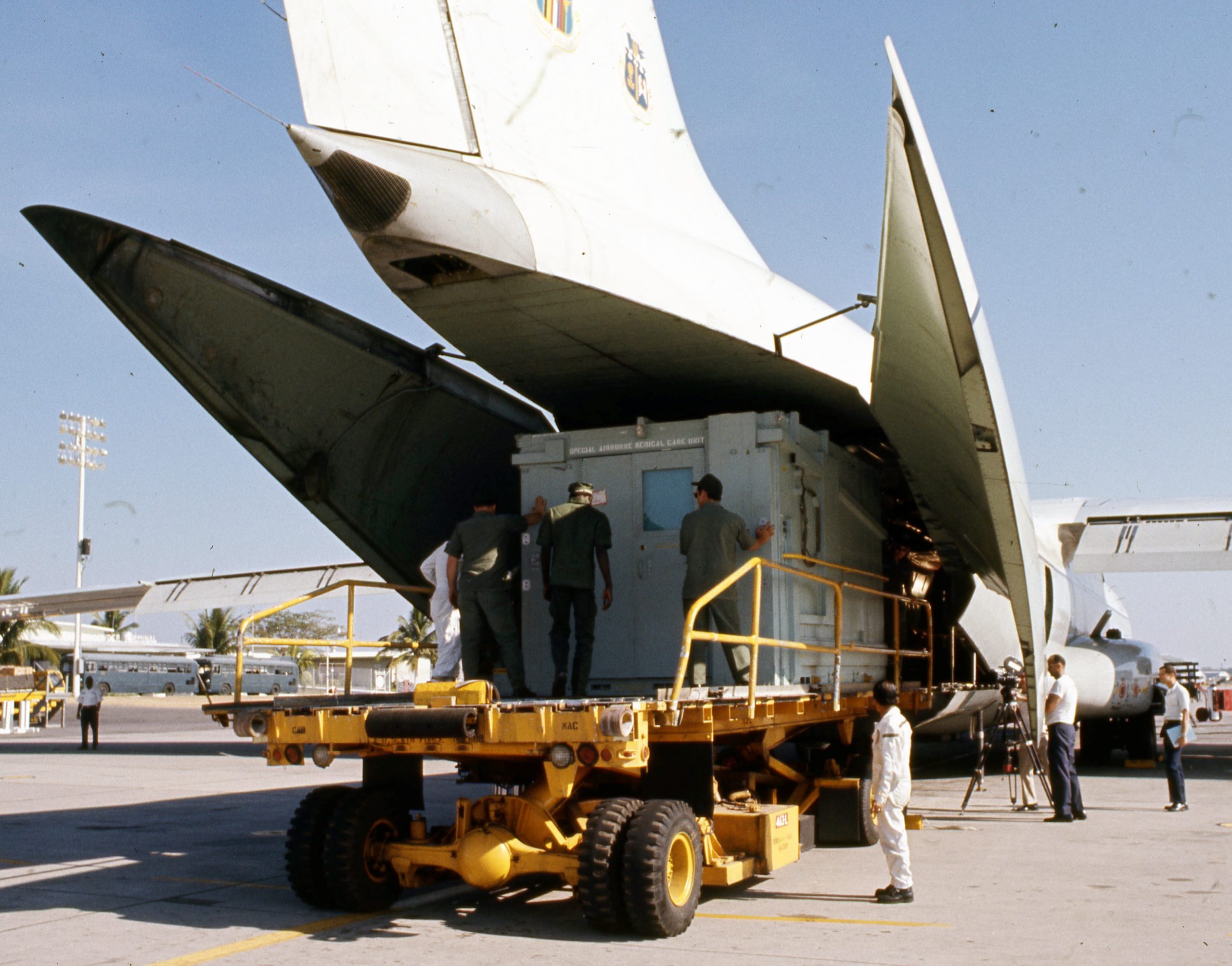
USAF photo sometime between March & April 1973, Clark Air Base, Philippines.
It was called Special Aerial Medical Care Unit (SAMCU), and could be environmentally controlled. However, the USAF had only one SAMCU, based in the Philippines, in case it was needed to evacuate extremely wounded personnel from Viet Nam. When looking at the photos of the SAMCU, notice how similar it looks to the ‘new’ NPC.
FEMA says pandemic isn’t done, BUILDING MASSIVE ISLAND HOSPITAL?
Going Viral: THE NEW TASK FORCE 31
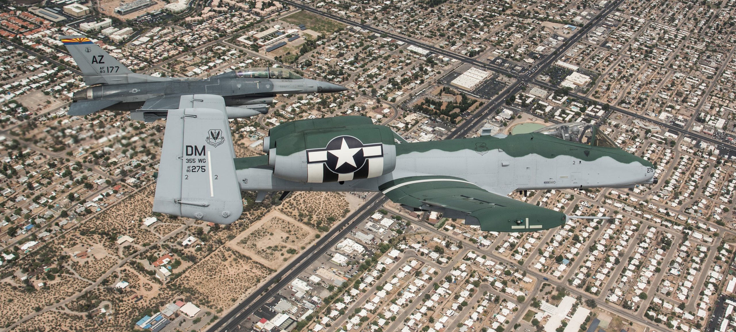
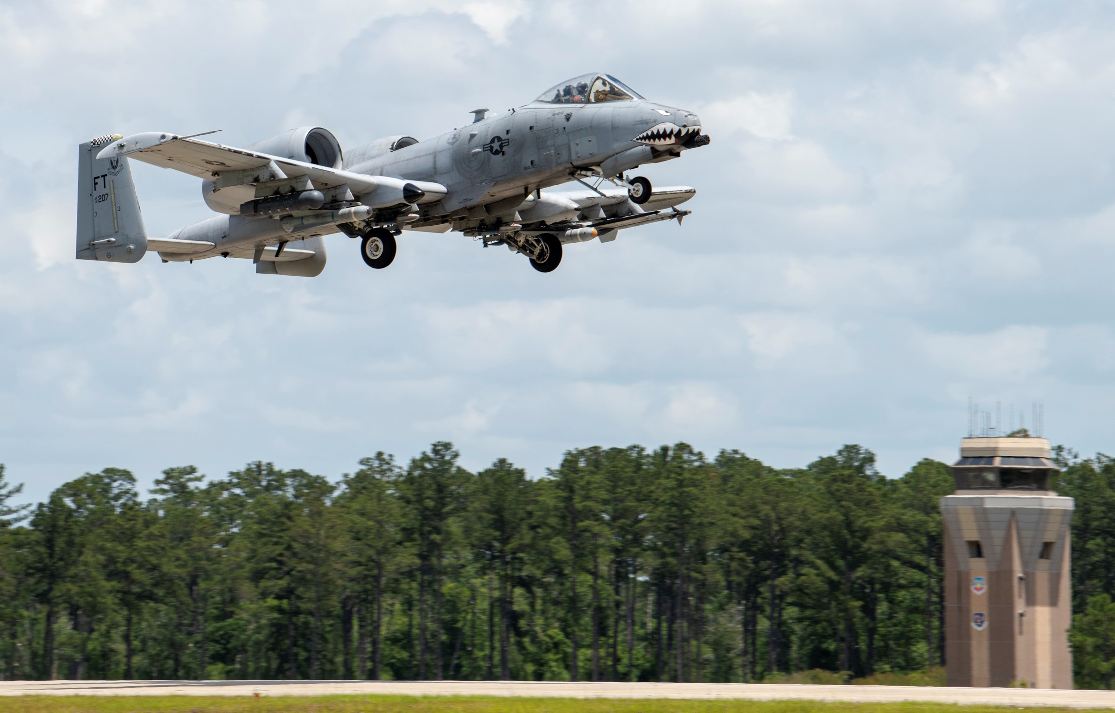
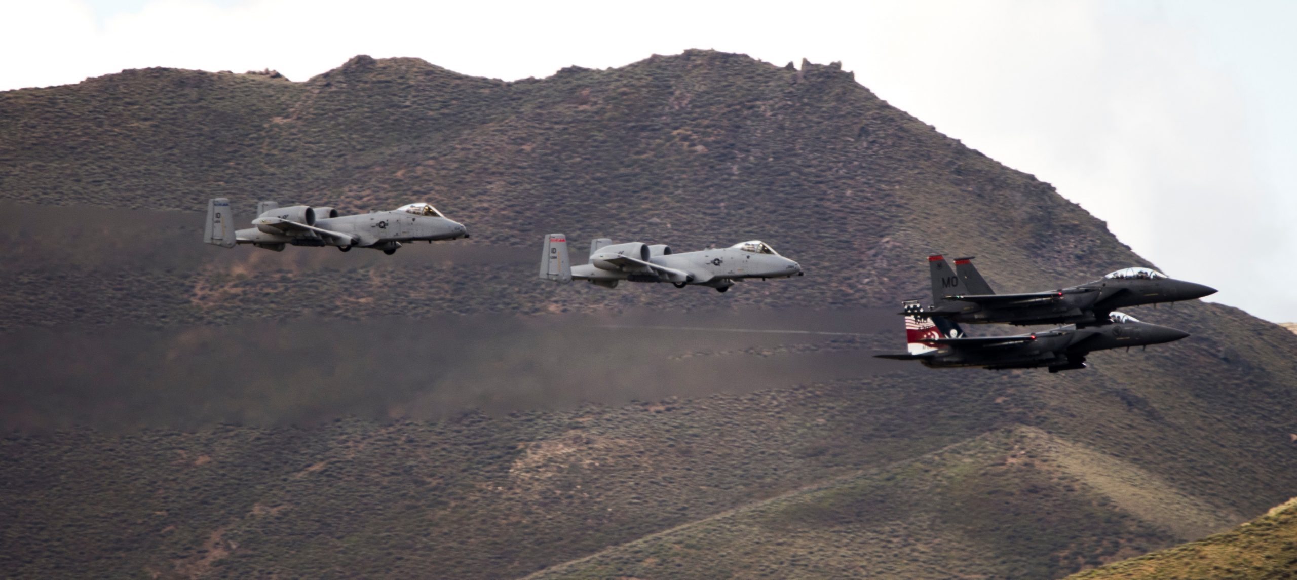
PANDEMIC OVERFLIGHT: A-10C (FOR COVID?) THUNDERBOLT-2


 Over Iraq, August 2017.

 Gulf of Alaska, June 2015.
 U.S. Marine Corps EA-6B Prowler refueling over Afghanistan, 30DEC2014.
 September 2011, Tactical Electronic Warfare Squadron 139 EA-6B gets fuel from Strike Fighter Squadron 154 F/A-18E Super Hornet.
 Somewhere over The Middle East, May 2011.
 Over Afghanistan, March 2011.
 Being refueled by F/A-18E Super Hornet over Austria, March 2009.
 Refueled by S-3B Viking off the coast of Japan, March 2008.
 Refueling over Kyrgyzstan, March 2006.
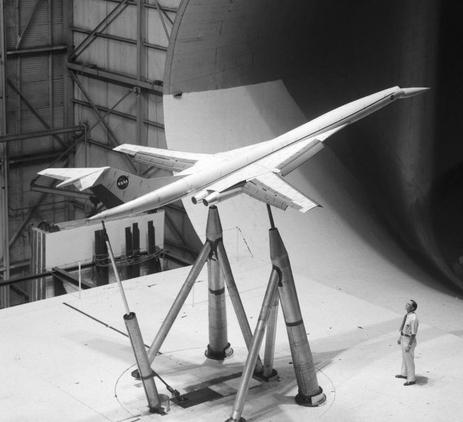


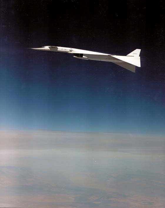
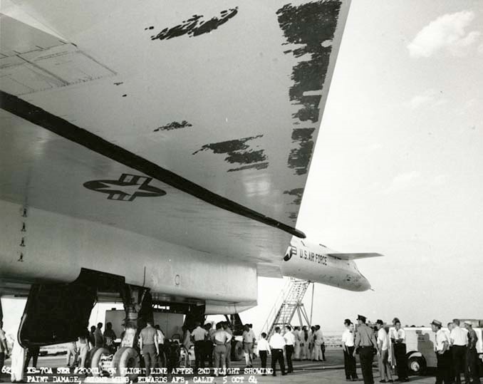 High Mach speed stripped the then standard thickness paint from the aircraft.


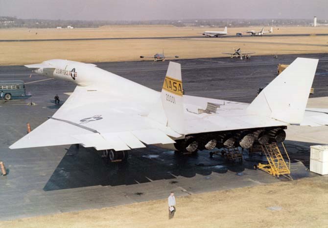 Valkyrie 20001 after arrival at Wright Patterson Air Force Base, February 1969.
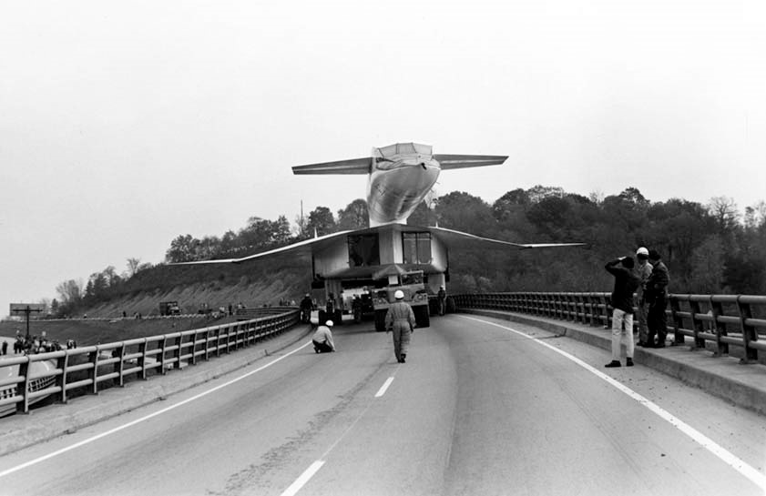 Being flown down the road to its retirement home known as a museum, 1971.

 Indiana Air National Guard 122nd Fighter Wing over Terre Haute, 02MAY2020.
 122nd Fighter Wing, Indiana Air National Guard, over Fort Wayne on 13MAY2020.
 Maryland Air National Guard 175th Wing A-10Cs over local hospitals, 08MAY2020.
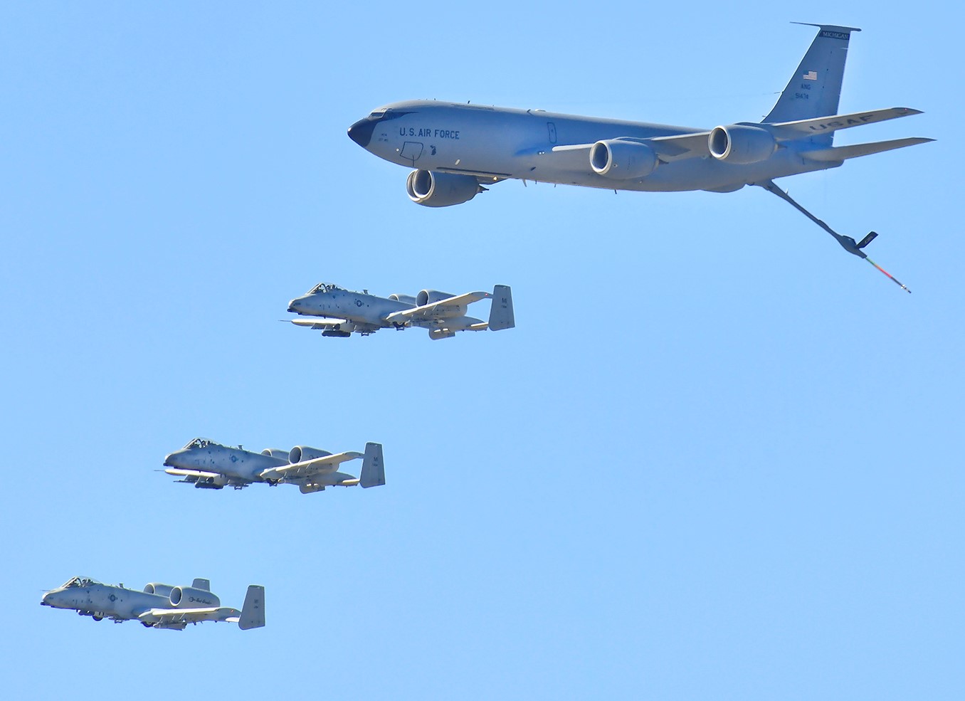


 A KC-135 leads a pack of F-16s and F-35s on a Air Force Salutes flight over Arizona, 01MAY2020. At least 15 aircraft were involved.
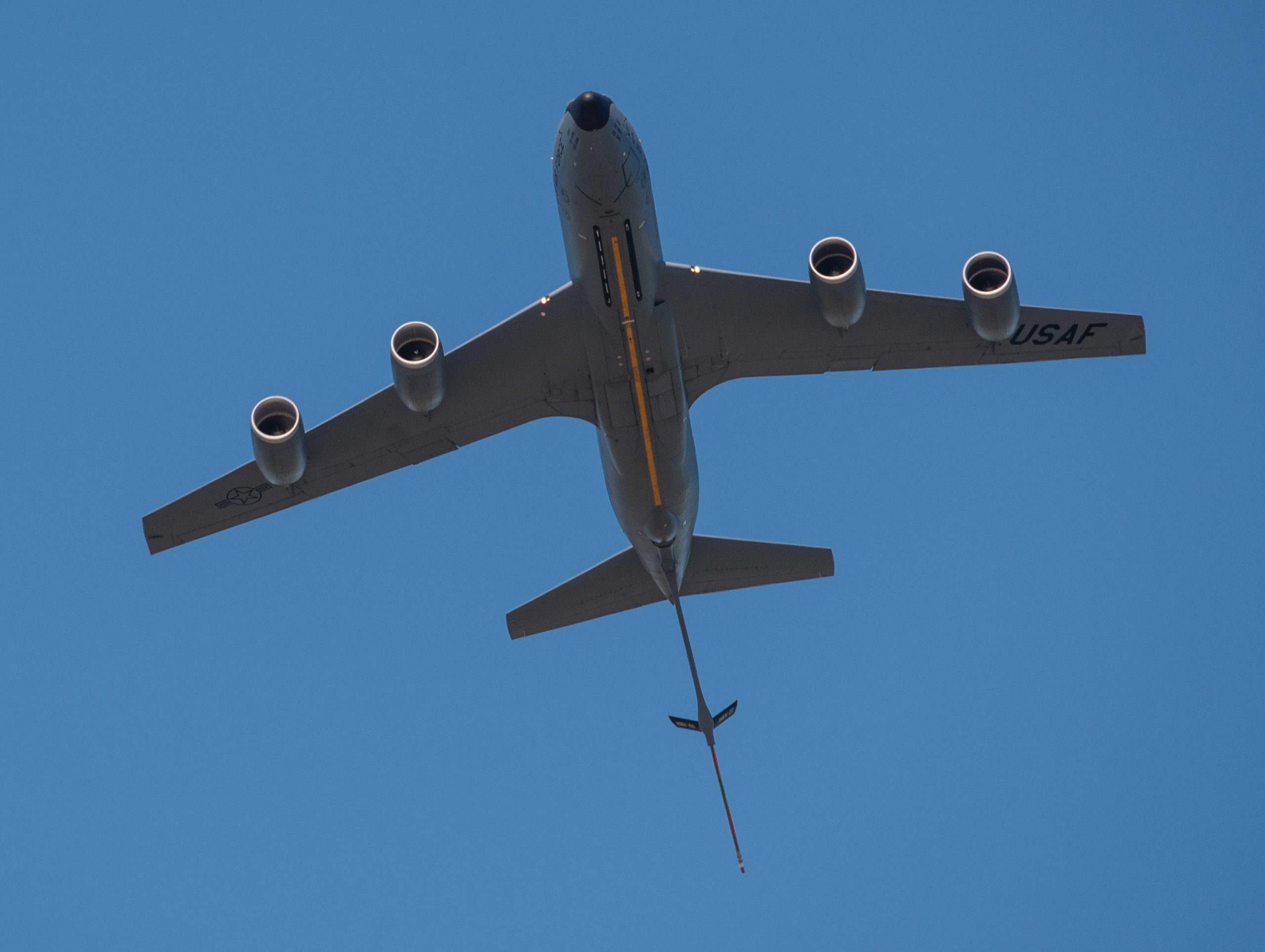
 The crew of a Michigan Air National Guard 127th Wing KC-135 just before taking off for a Michigan Strong flyover, 13MAY2020.
 KC-135R from the 914th Air Refueling Wing, Niagara Falls Air Reserve Station, in formation with F-35s from the 158th Fighter Wing, Vermont Air National Guard Base, 12MAY2020.
 Ohio Air National Guard KC-135 flies with an F-16 during Operation American Resolve, 13MAY2020.
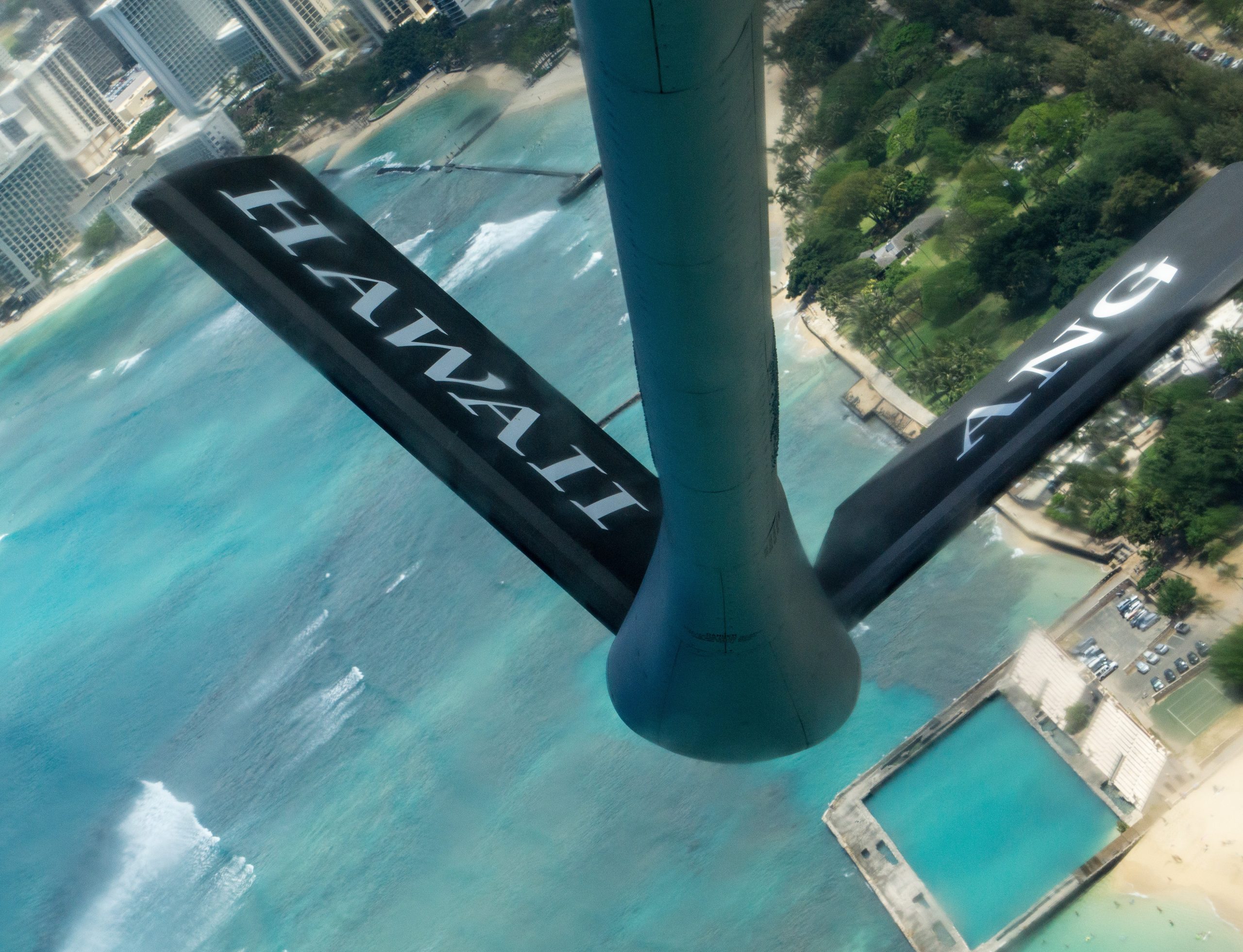
 Tail boom of 134th Air Refueling Wing, Tennessee Air National Guard, 12MAY2020.
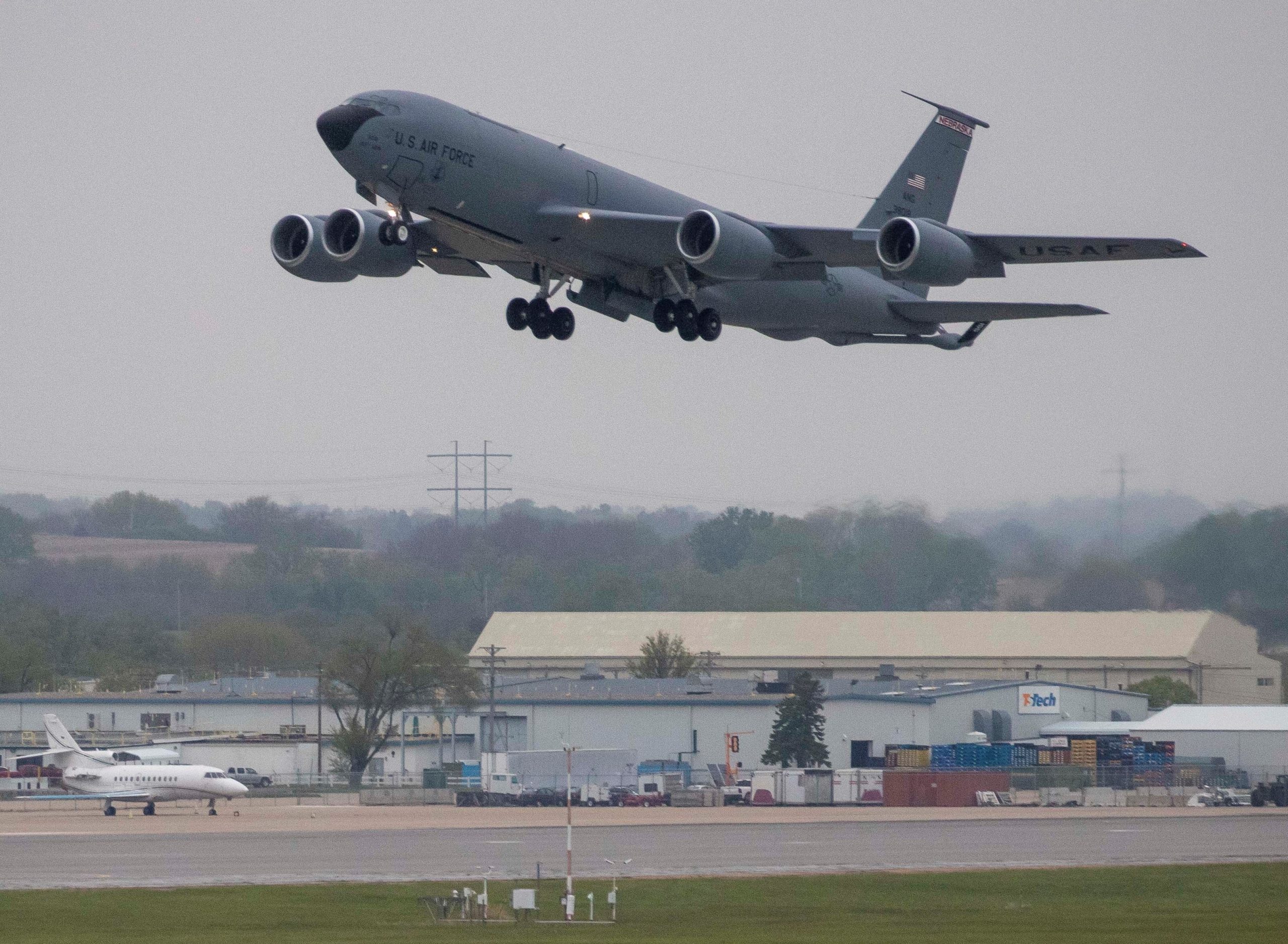

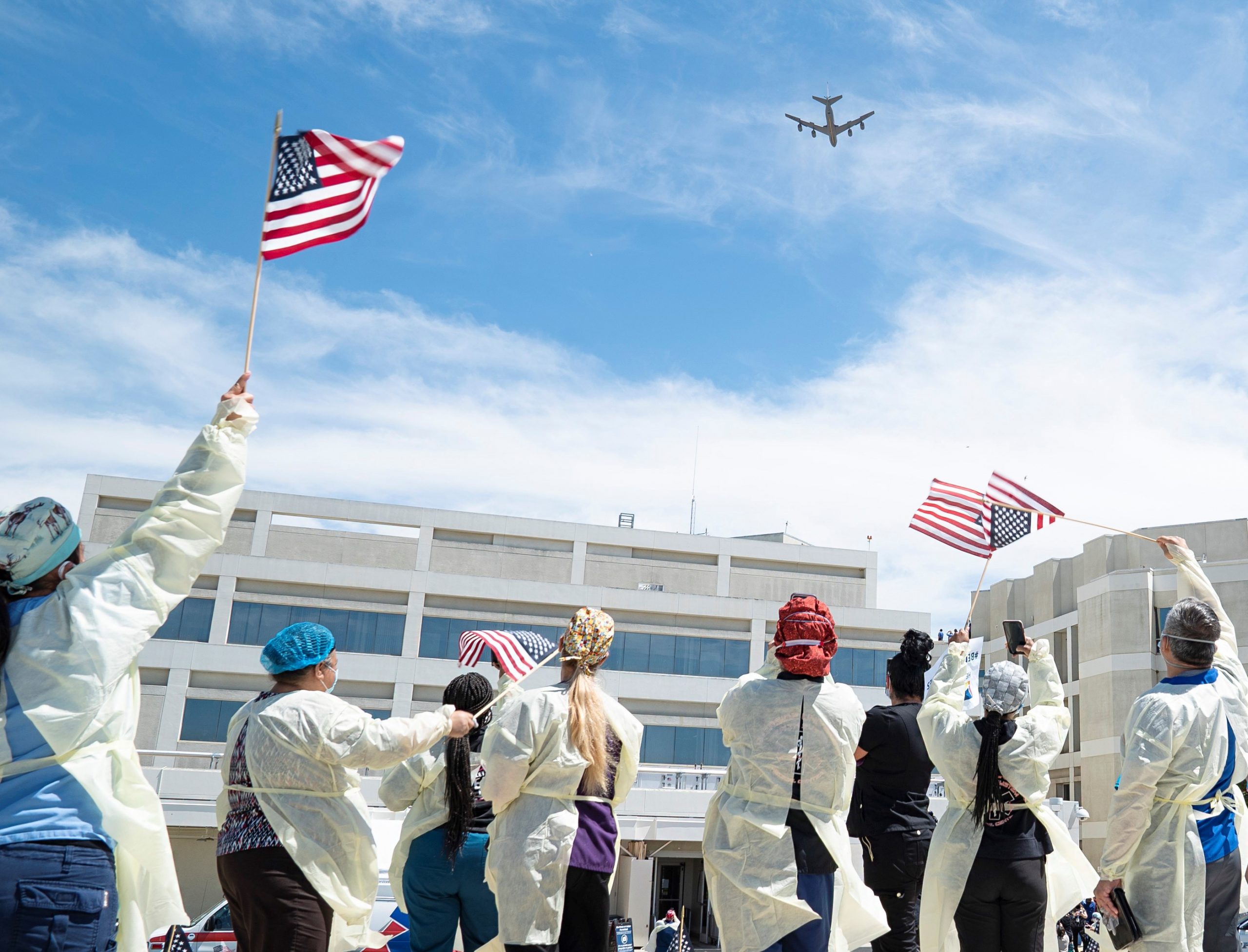
 Reflection of Little Rock Air Force Base C-130J in the windows of a Arkansas hospital, 08MAY2020.
 California Air National Guard’s 115th Airlift Squadron over the Mojave Desert near Palmdale, 14MAY2020.
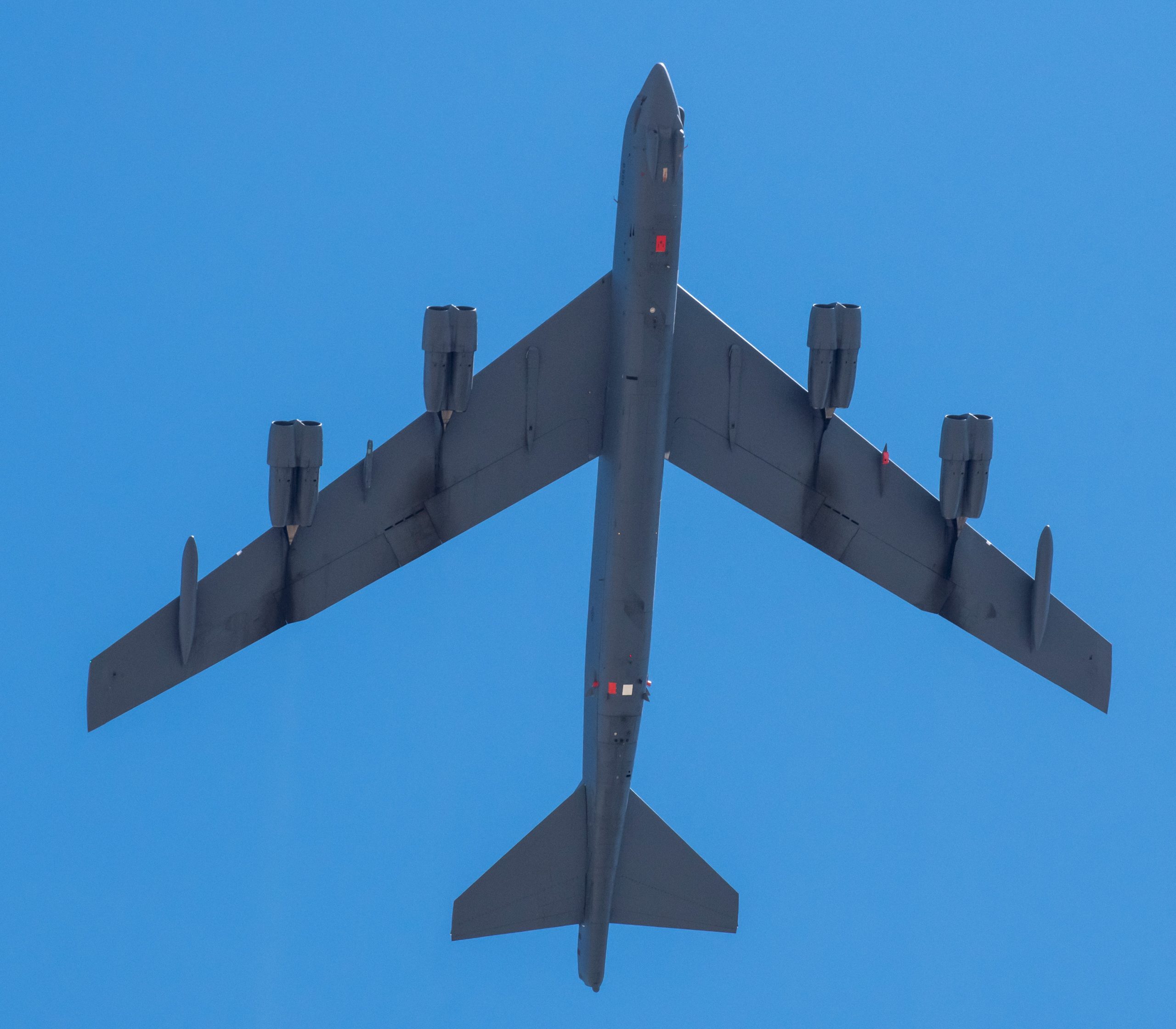
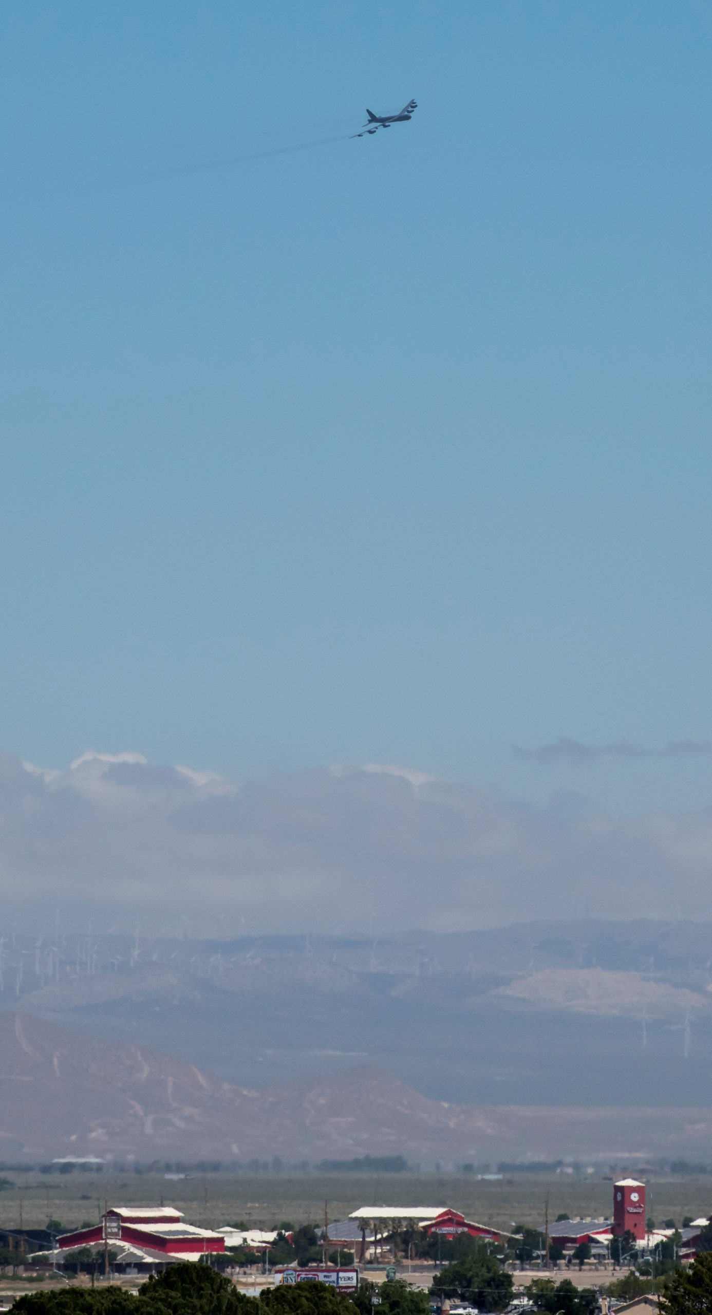

 403rd Wing’s 815th Airlift Squadron over Mississippi’s Gulf Coast, 28APR2020.

 New York Air National Guard LC-130 (
 A C-130H out of Youngstown Air Reserve Station, Ohio, conducting a second round of pandemic overflights on 07MAY2020. Not only did Ohio aircraft fly over Ohio, but also locations in Pennsylvania.
 Two Ohio Air National Guard 179th Airlift Wing C-130Hs also flew pandemic overflights, 15MAY2020.
 Naval Air Station Joint Reserve Base Fort Worth, Texas, this Blue Angels C-130 was temporarily brought out of retirement to give moral support, 06MAY2020, unfortunately it was not flown.