
Incomplete list of links to news reports about viral outbreaks from the week leading up to the 13th of the Gregorian month of May 2020. These outbreaks tell us one thing for sure; no healthcare system anywhere in the world can handle outbreaks of multiple diseases, let alone one pandemic.
Thailand reveals various viral infection numbers as of May 5th: Dengue; 10,938 with nine deaths
Chikungunya; more than 10-thousand
CoViD-19; 3,015 with 56 deaths
Measles; at least 765 infections
Stay-at-home lockdowns contradict proven ‘open-air’ treatment for infections: “Solar radiation may retard its transmission by directly inactivating virions and by increasing immunity to them. A combination of outdoor air and sunlight could also reduce the likelihood of secondary respiratory infections.”
FLU=INFLUENZA
Revealed; face masks used during 1918 Spanish Flu failed to stop the pandemic
COVID-19=CORONAVIRUS DISEASE 2019
U.S. CDC reports 16,318 laboratory-confirmed COVID-19-associated hospitalizations between March 1, 2020, and May 2, 2020. The CDC’s death rate percentage cannot be cited for CoViD-19 rates because it admittedly uses deaths from pneumonia and influenza in factoring the CoViD-19 death rate. Apparently doing so is the only way to put CoViD-19 death rate above the ‘epidemic’ level.
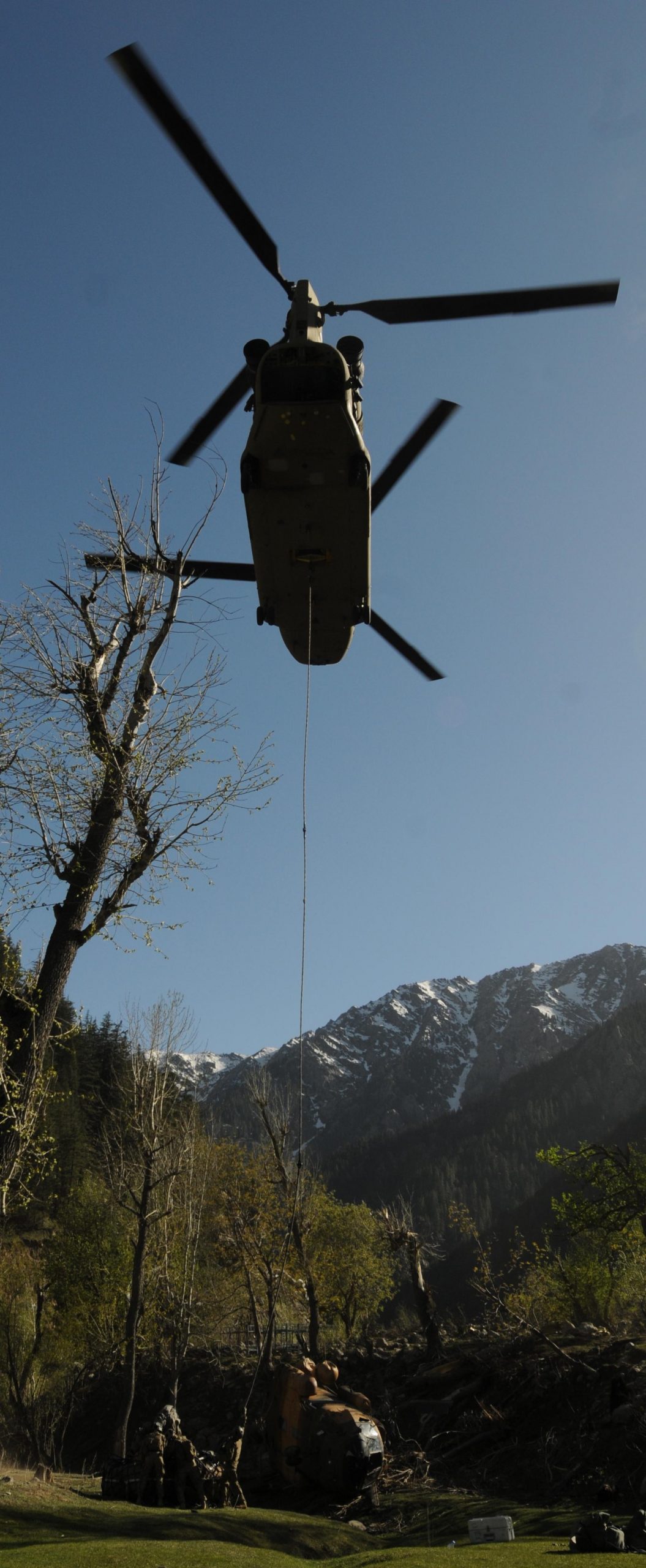
 CoViD-19 medical supplies arrived at Bagram Airport and are being distributed to U.S. Forward Operating Bases around Afghanistan.
While the U.S. was sending CoViD-19 supplies to troops in Afghanistan, NATO member Turkey sent CoViD-19 supplies to the United States.  On 28APR2020, a Turkish Airbus A400M loaded with medical Personal Protective Equipment landed at Joint Base Andrews in Maryland.
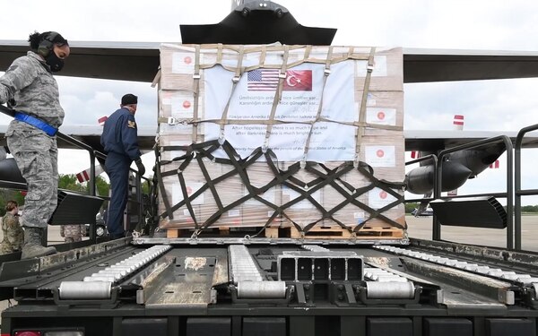 Then on 01MAY2020, a Turkish C-130 landed at the same base with even more PPE.
Wuhan, China, orders new testing after new infections
Prisoners in California intentionally infected themselves
DENGUE=DENGUE HEMORRHAGIC FEVER, aka Breakbone Fever
Focus on CoViD has resulted in Dengue epidemic across Southeast Asia
Focus on CoViD has resulted in Dengue epidemic across Latin America
25-thousand confirmed infections in Argentina
U.S. Army hospital discovers how your immune system reacts to Dengue
CHIKUNGUNYA

Under what I call Operation Jupiter, the U.S. Defense Threat Reduction Agency’s Chemical and Biological Technologies Department issued the above map of past Chikungunya outbreaks stating that health organizations need to prepare for a future pandemic! Their warning is based on a new computer app called CHIKRisk.
LASSA=LASSA MAMAMMARENAVIRUS, aka LASSA HEMORRHAGIC FEVER
Nigeria reporting 991 confirmed infections, 191 deaths since January
.
HANTAVIRUS
RABIES=LYSSAVIRUSES (considered 100% fatal without treatment)
 Rabies is so bad in Turkey that U.S. military personnel on Incirlik Air Base are being told that “A common misconception is that animals infected with rabies virus ‘look rabid’. Animals infected with rabies virus can spread the virus to humans and other animals prior to showing clinical signs of illness. In addition to rabies, there are many other infectious diseases that can be spread from stray animals to humans. These diseases can be anything from severe wound infections to parasite infections. Rabies virus has a 100% mortality rate if left untreated.”-Captian Timothy Beck, U.S. Army, Incirlik Veterinary Services
Bat found on balcony in Fremont, California, infected with rabies
New Mexico reports three cases of rabid skunks attacking humans and dogs
Vanderburgh County, Indiana, reports rabid bat
Baltimore County, Maryland, reports rabid coyote pack attacking dogs
Whitestown, New York, reports rabid raccoon
Fox that was biting hikers in North Carolina was infected with rabies
Hall County, Georgia, reports fourth rabies case this year
Going Viral: PALE HORSE, “STOP SAYING IT’S A BAD FLU!”
RECORD SETTING PANDEMIC AIRBRIDGE CONTINUES
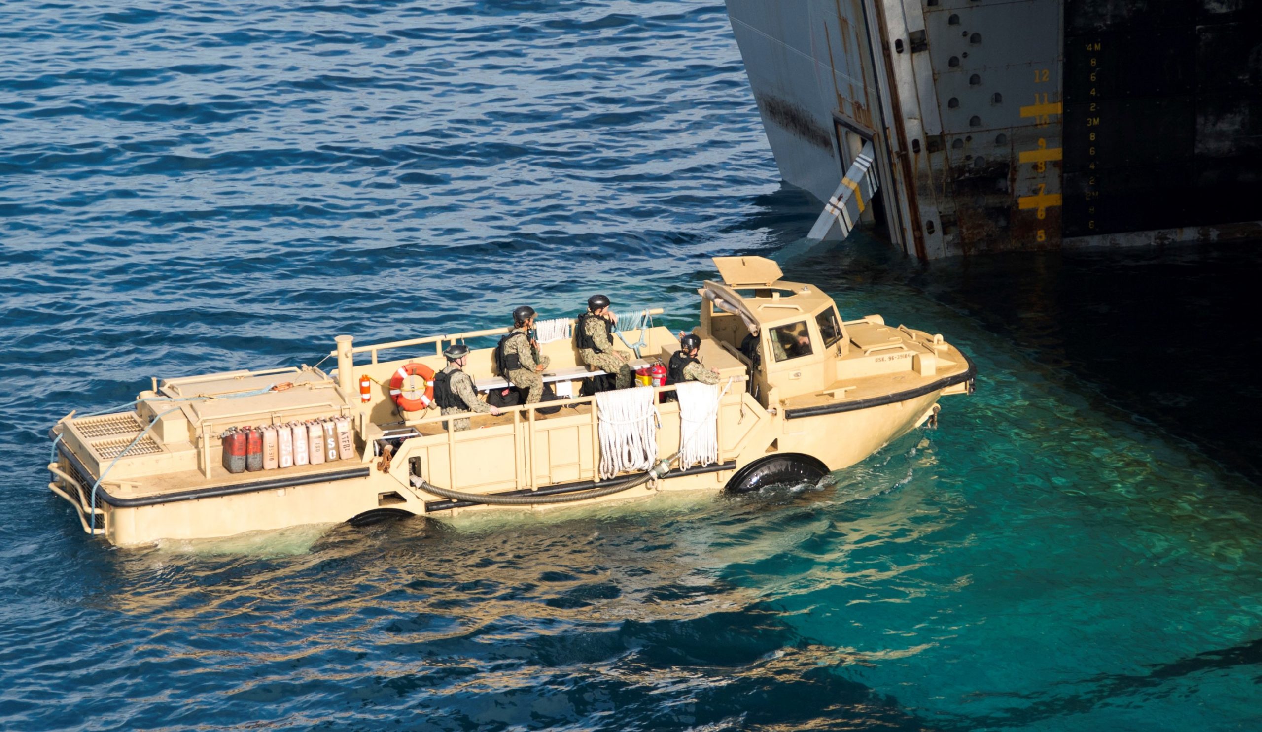
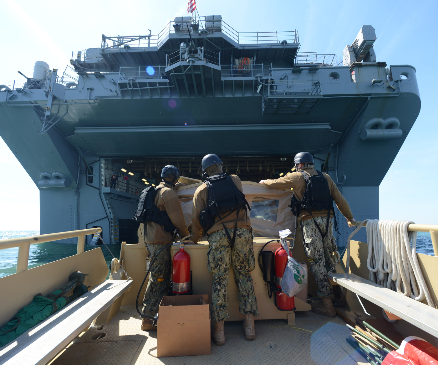
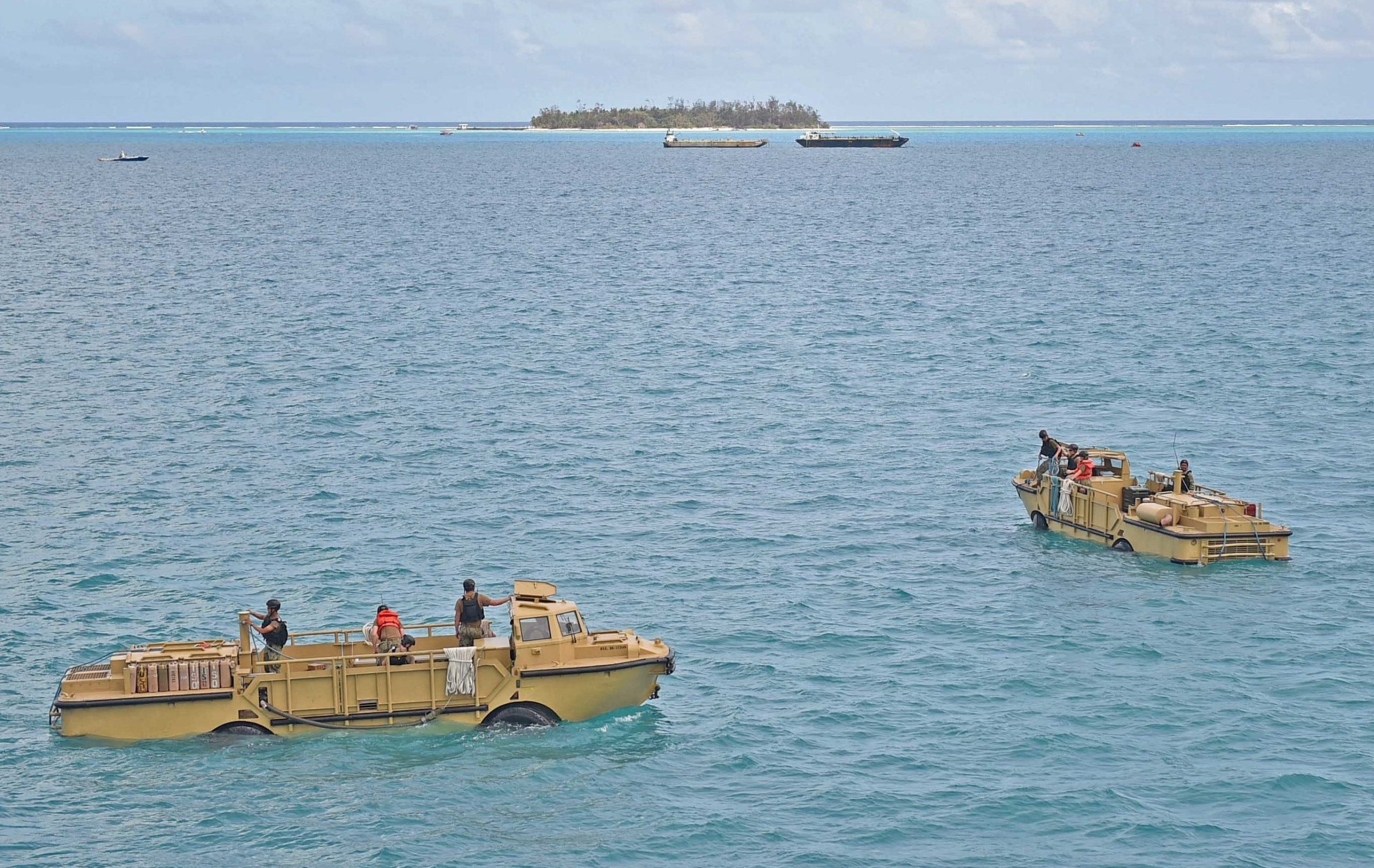
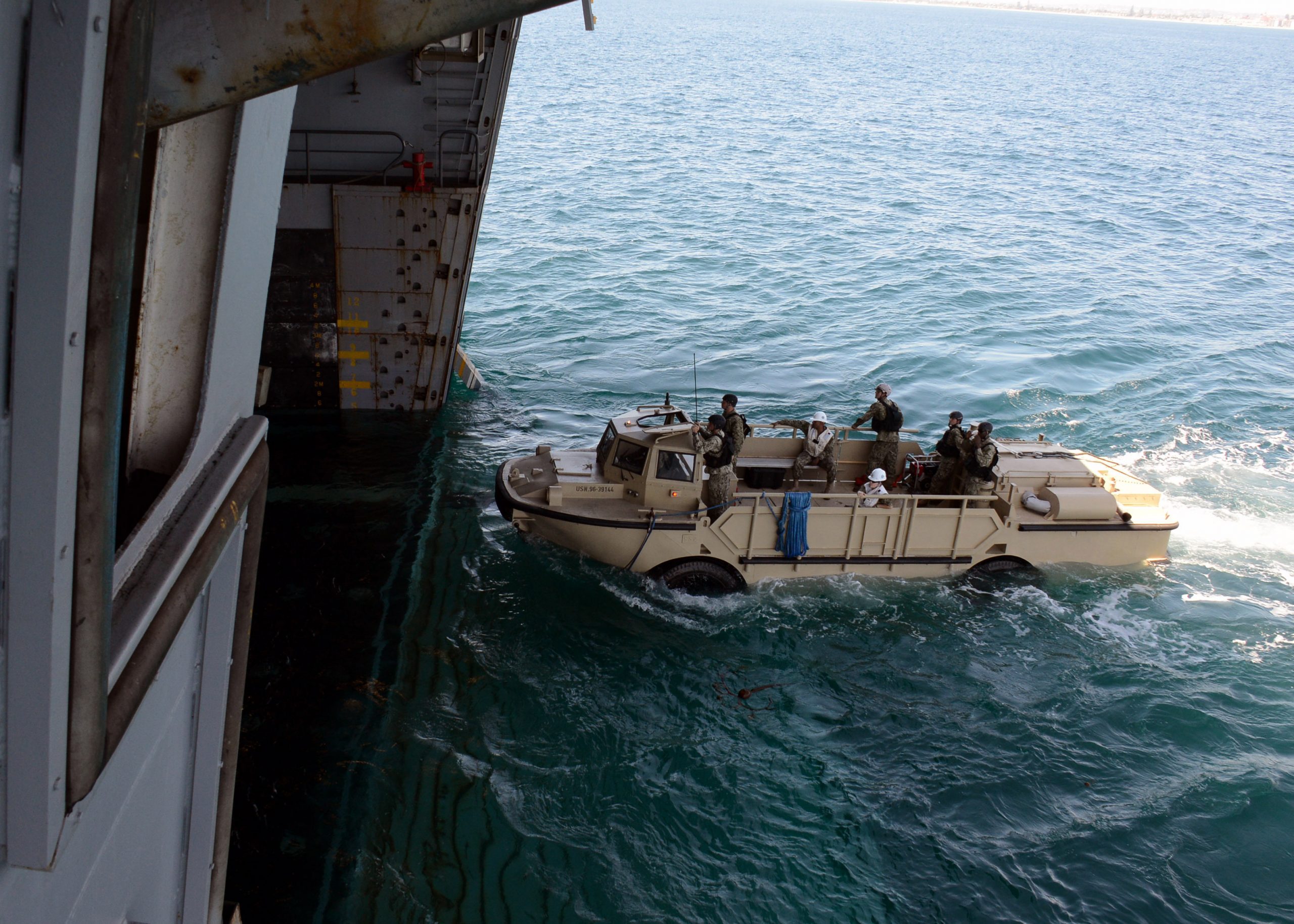
FEMA BUILDING MASSIVE ISLAND HOSPITAL?
PANDEMIC REVEALS U.S. DEPENDENCE UPON FOREIGN FOOD!
Pandemic Oddities: IF YOU’RE SICK YOU’RE NOW A TERRORIST! VEGGIE PANIC BUYING! ANIMALS BEING SLAUGHTERED, BUT NOT FOR FOOD!

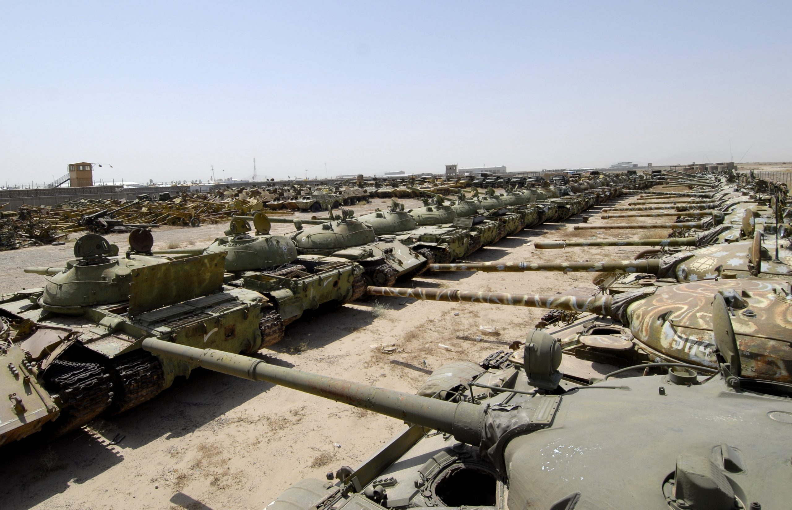
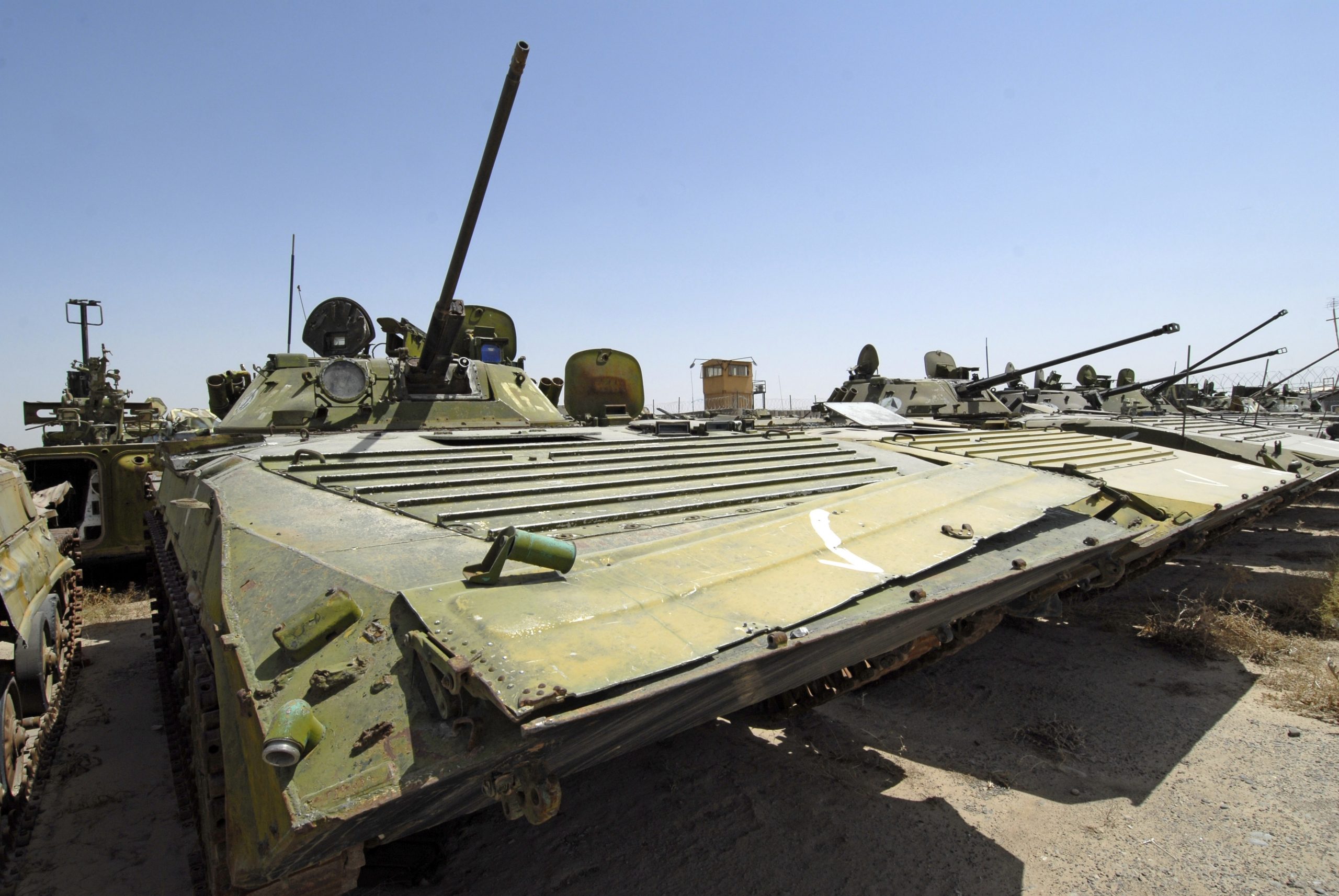
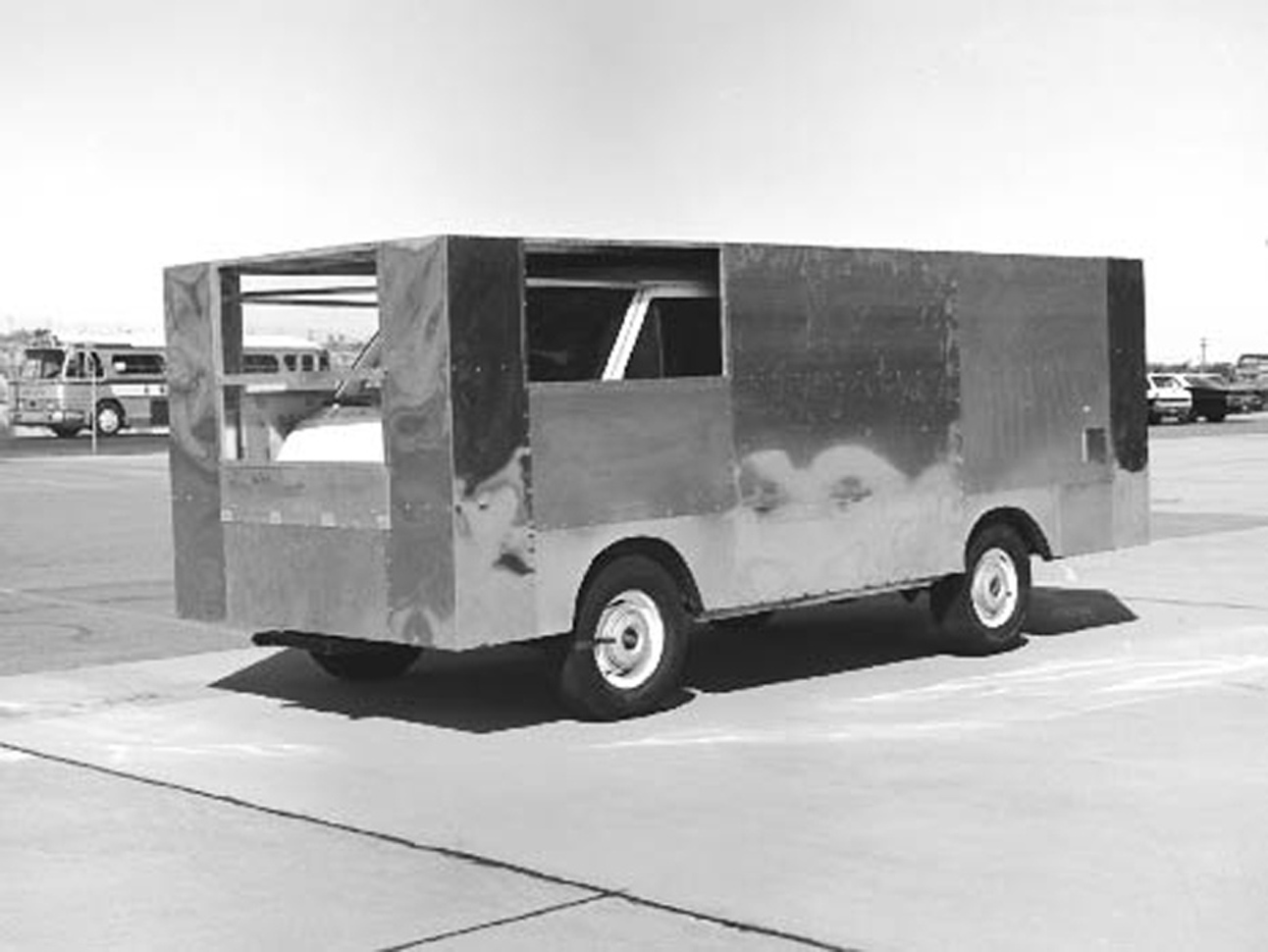
 Camp Shaheen.
 November 2010, a maintenance supervisor with Company D, 186th Brigade Support Battalion, 86th Infantry Brigade Combat Team cuts-up an old Soviet occupation armored vehicle in Durani Village, Parwan Province, Afghanistan. The villagers were able to sell the pieces of steel to recyclers for cash.
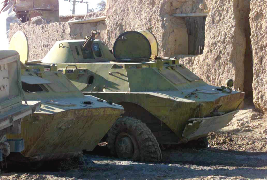
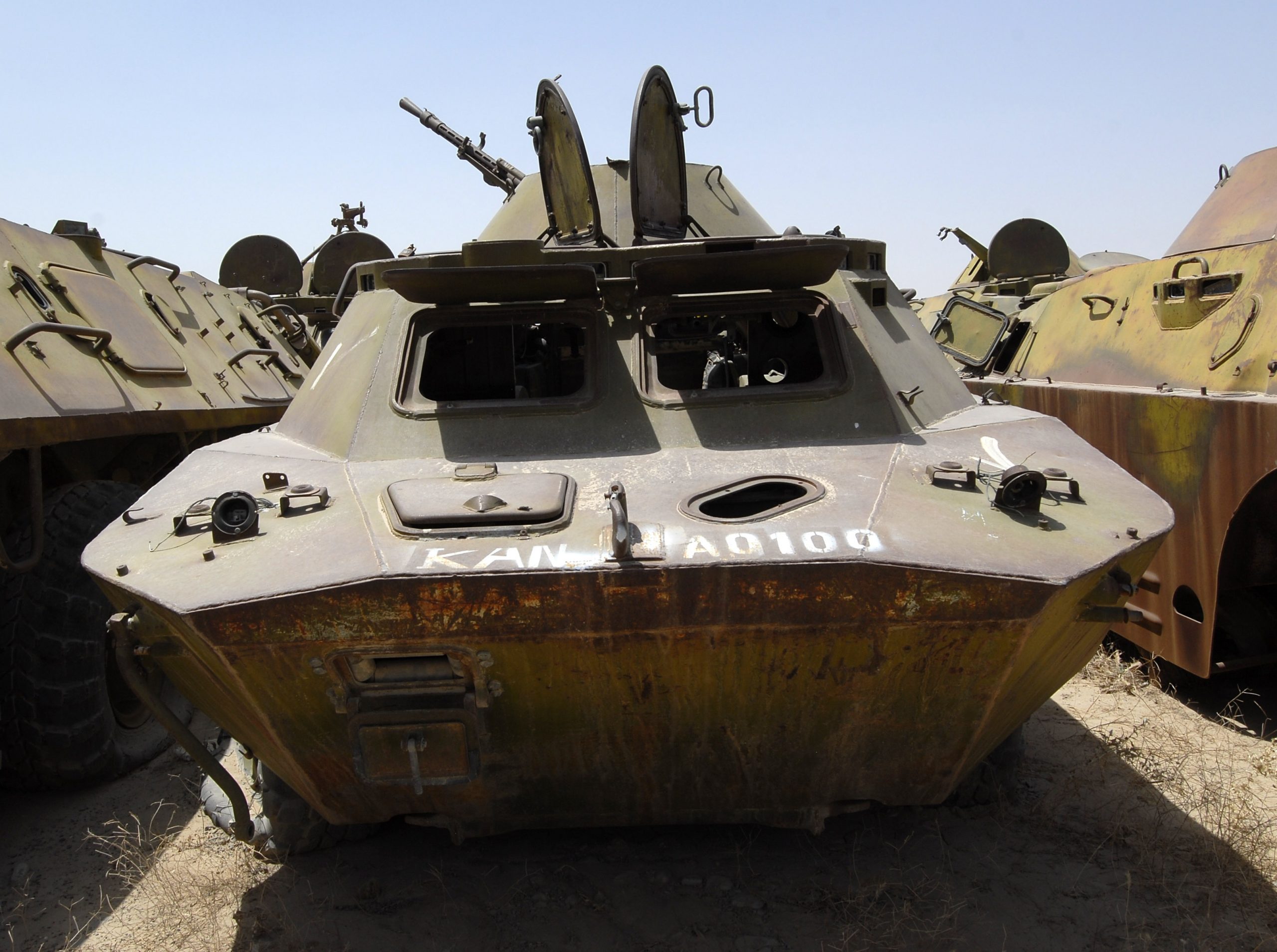
 BTR-80, Panjshir Province, Afghanistan, January 2010.
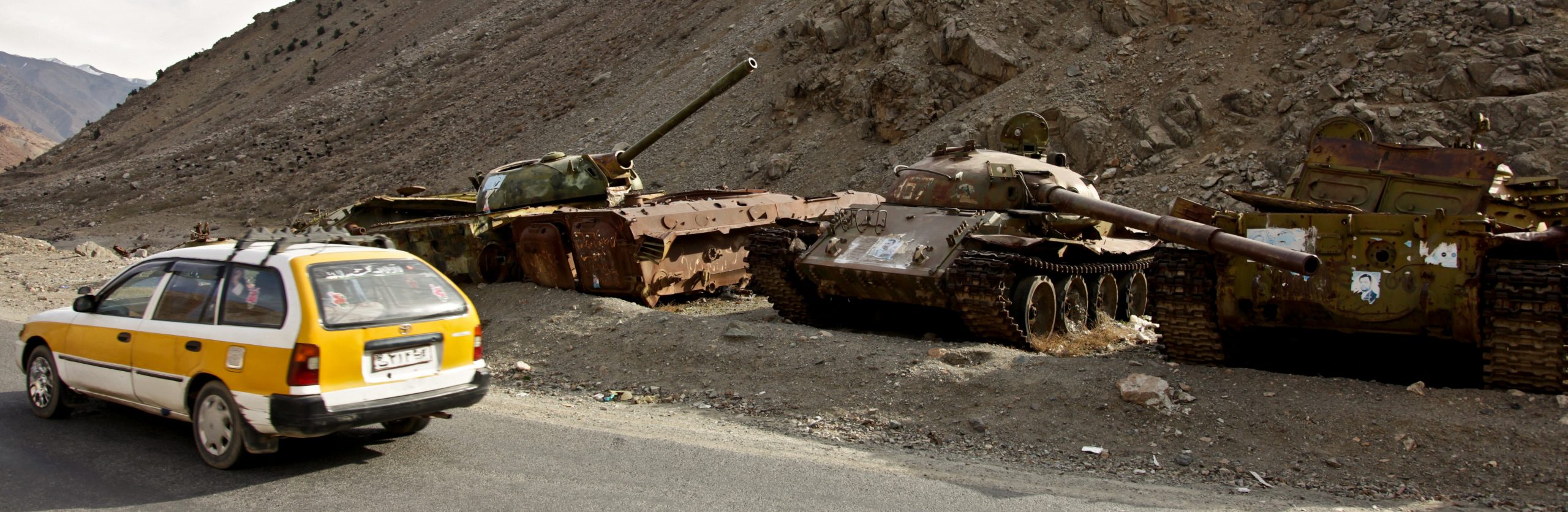

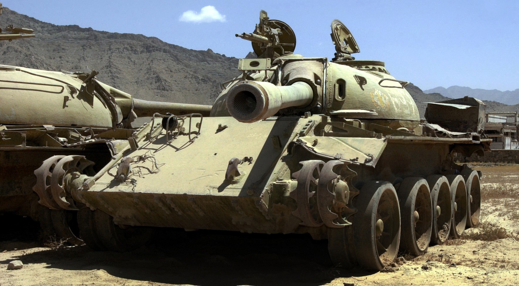
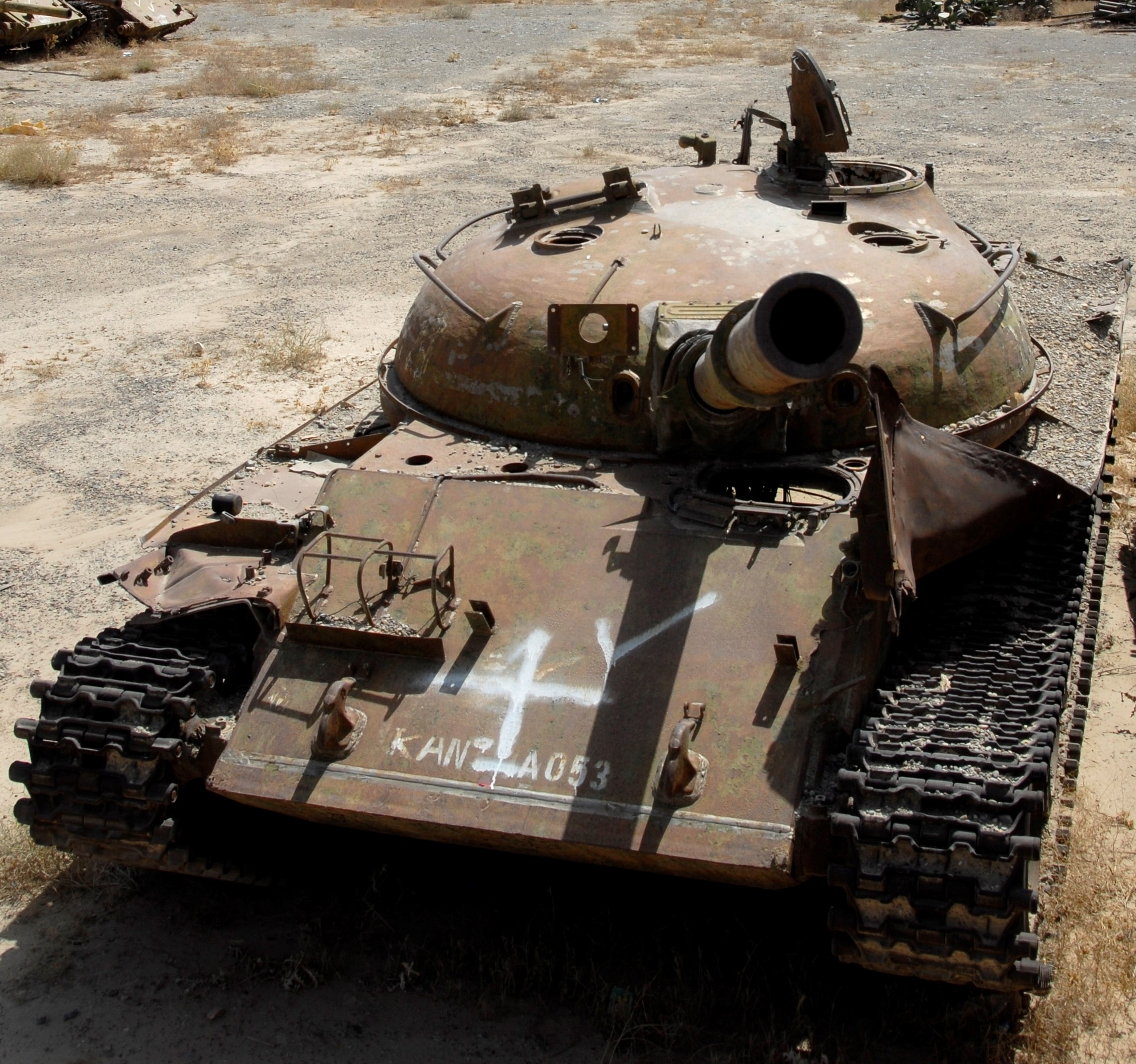
 T-54/55, Bamyan Province.
 Nowzad, Helmand Province, Afghanistan, February 2011. Children line up for school while a relic (T-55) of the 1980s Soviet occupation rusts away in the background.
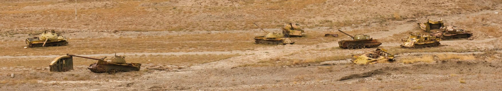
 Derelict World War Two era Soviet T-34/85 in Muqer District, Ghazni Province, March 2012.
 T-55 in Nowzad, Helmand Province, Afghanistan February 2012.
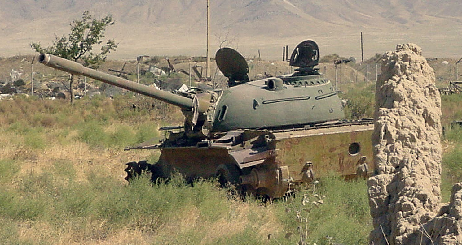
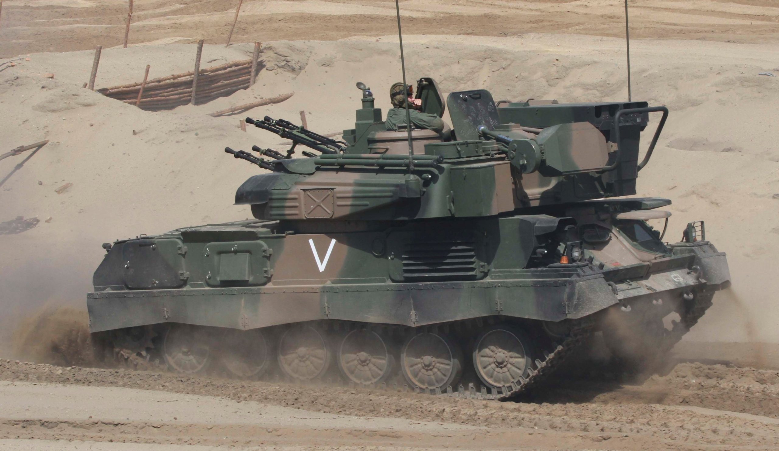
 Remains of ZSU-23-4, Bala Hissar Fortress, August 2013. You can see where the anti-aircraft tank took a direct hit in the side.
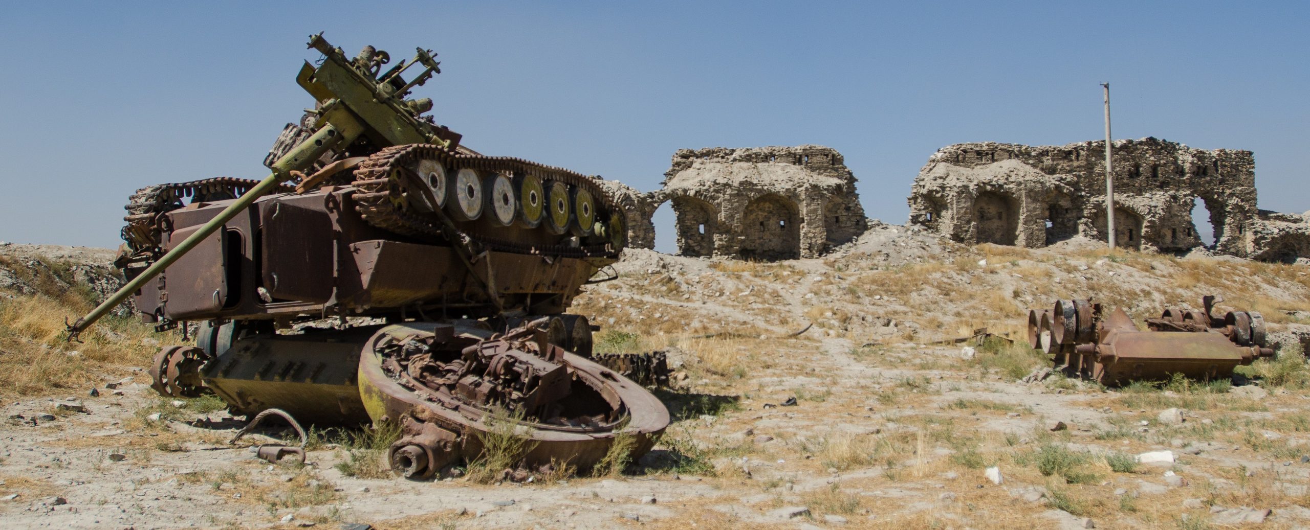
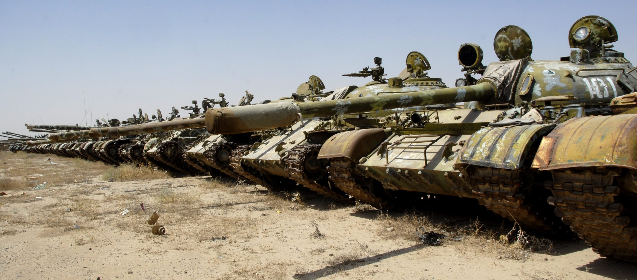
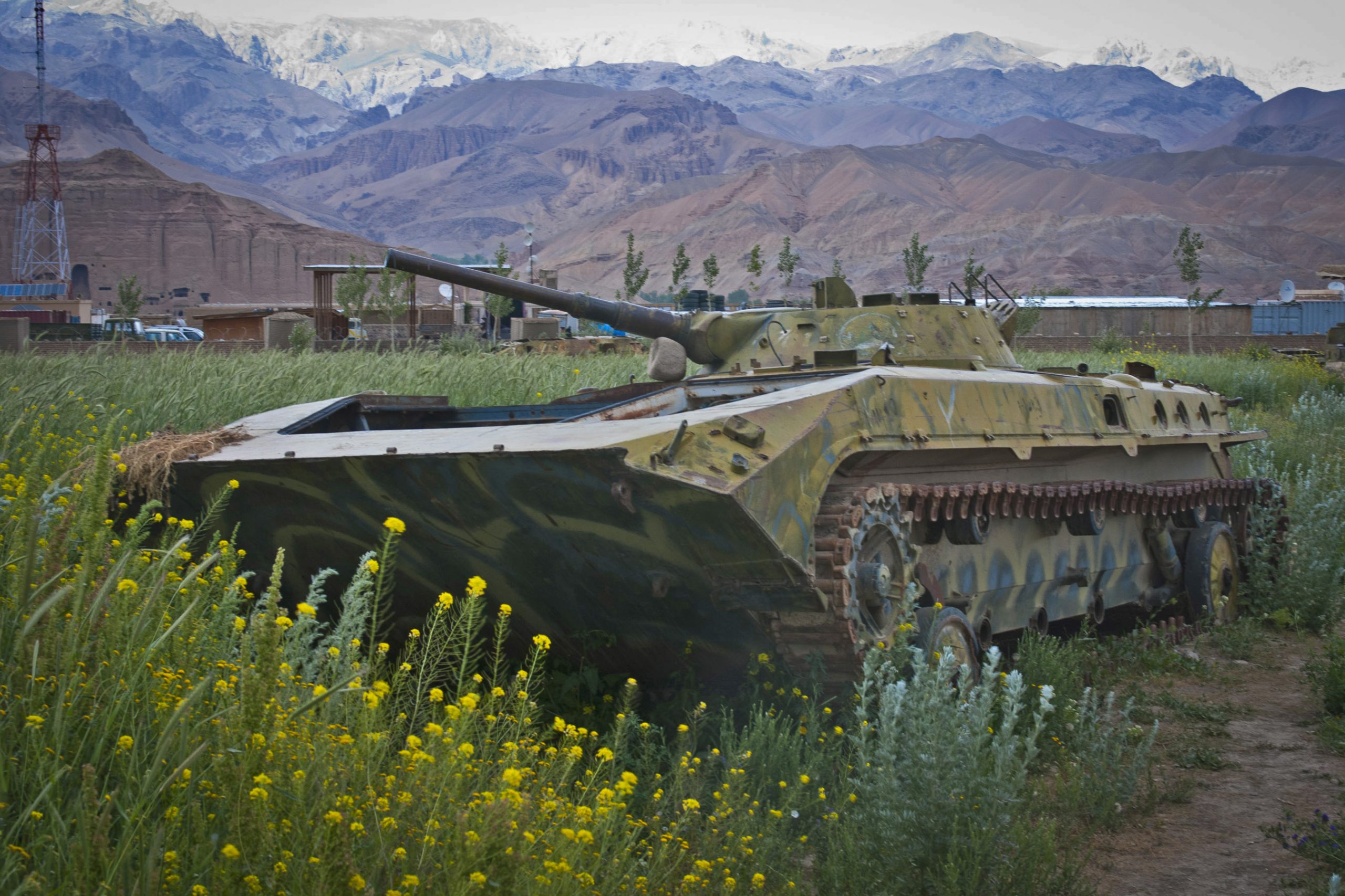
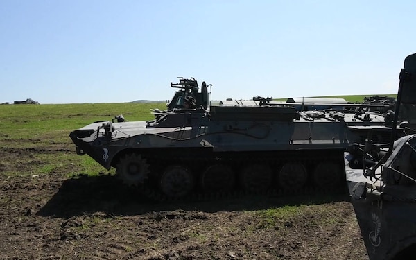
 BMP-1s and a T-54/55 (without bore evacuator) in Bamyan Province, February 2013.
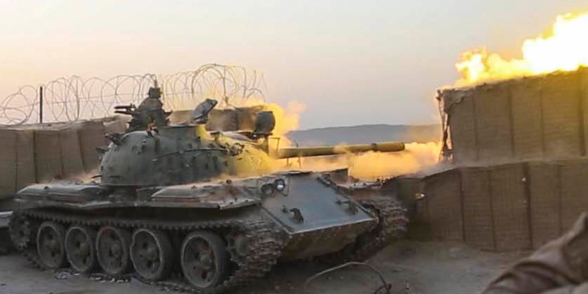
 Soviet occupation era T-55 still in use. The U.S. Marine Corps observed Afghan government forces use it against rebel troops in Sangin District, Helmand Province, August 2018.
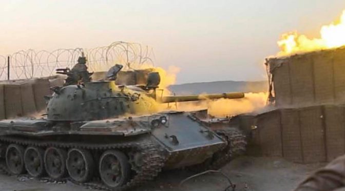


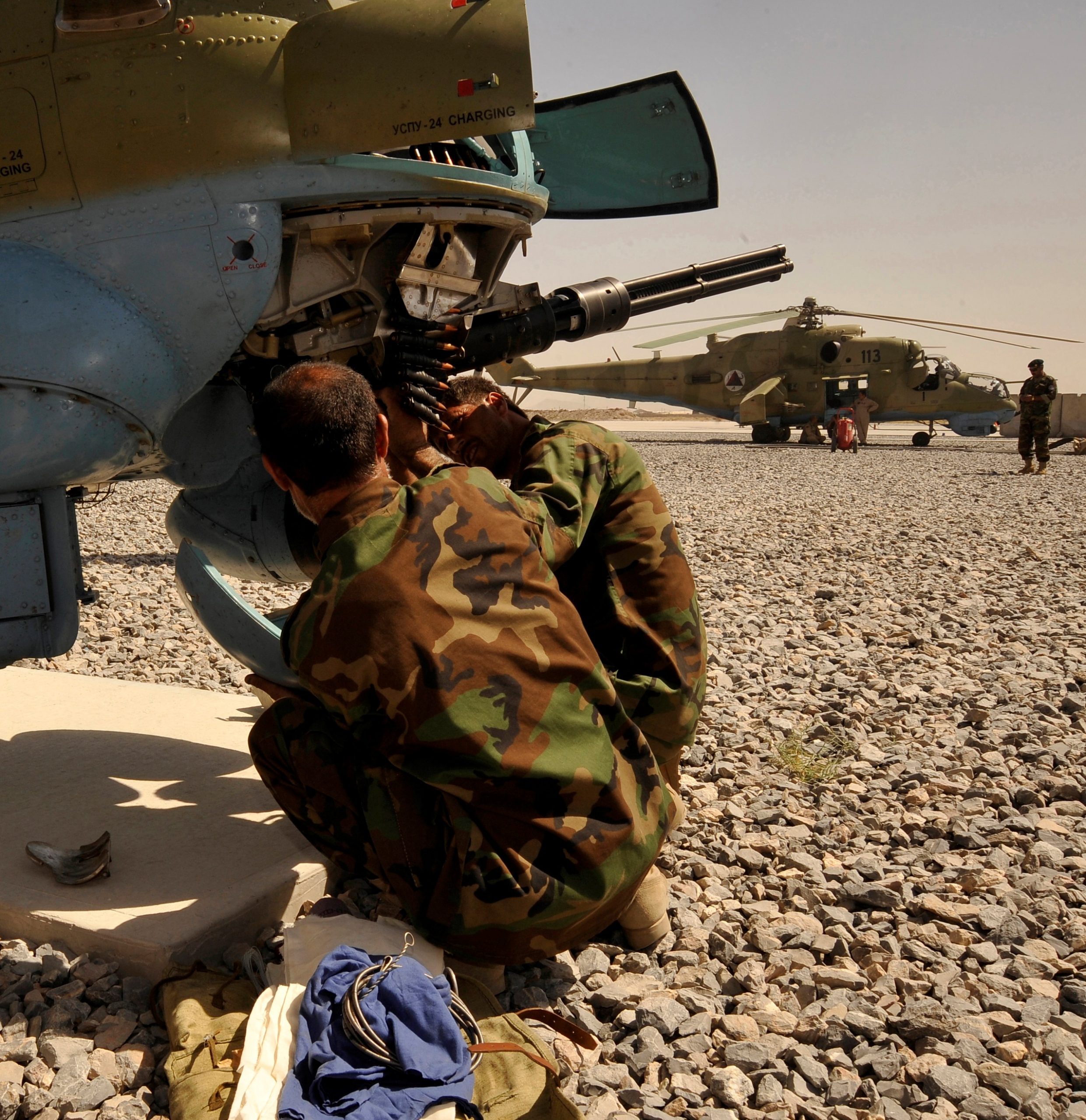


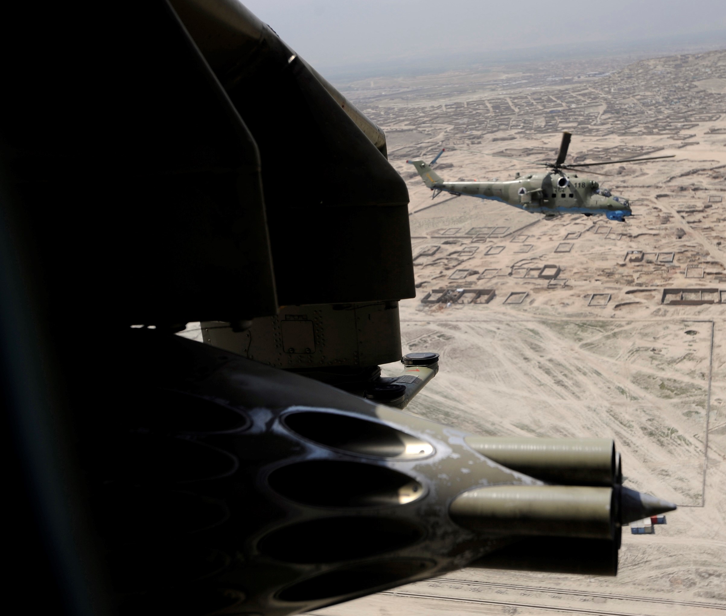
 Don’t forget the 57mm rockets.


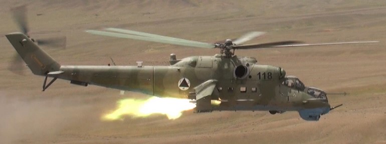


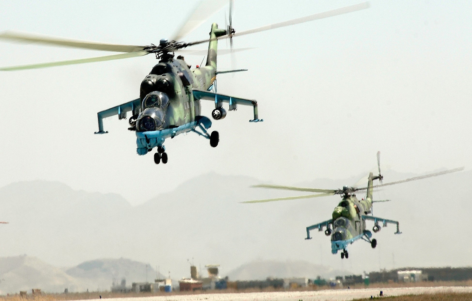
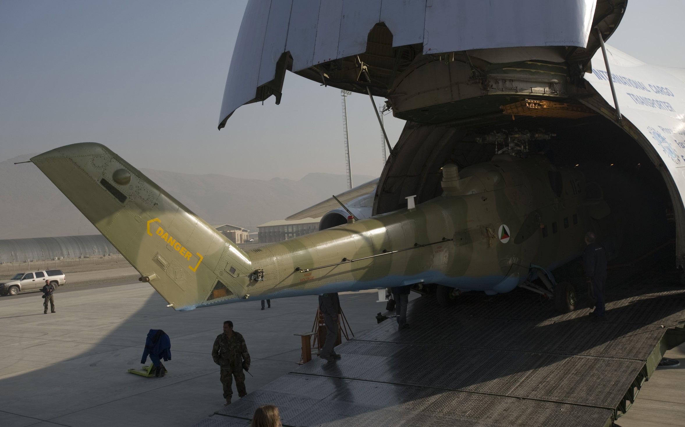
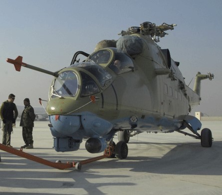
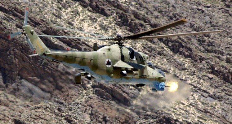
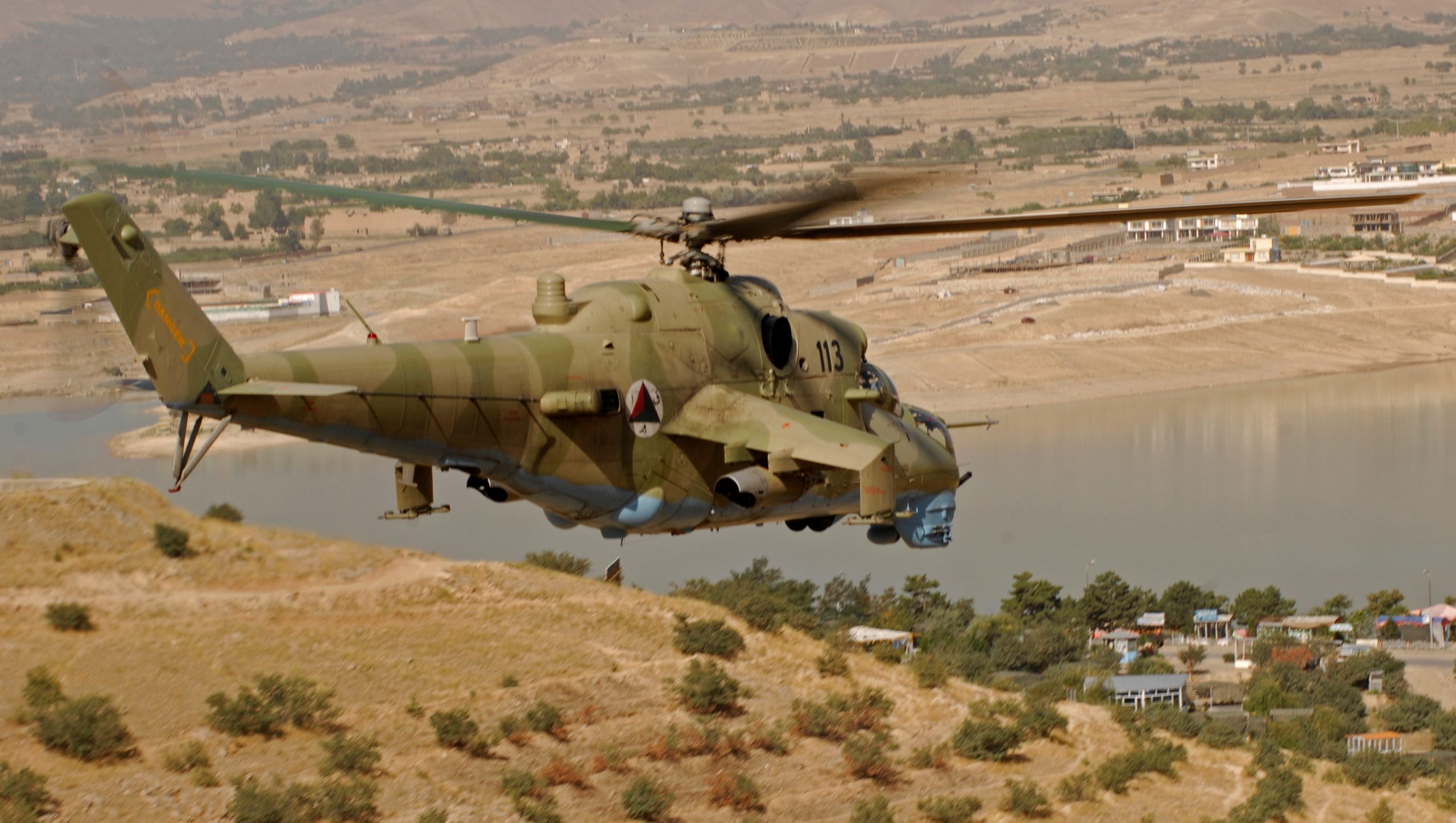
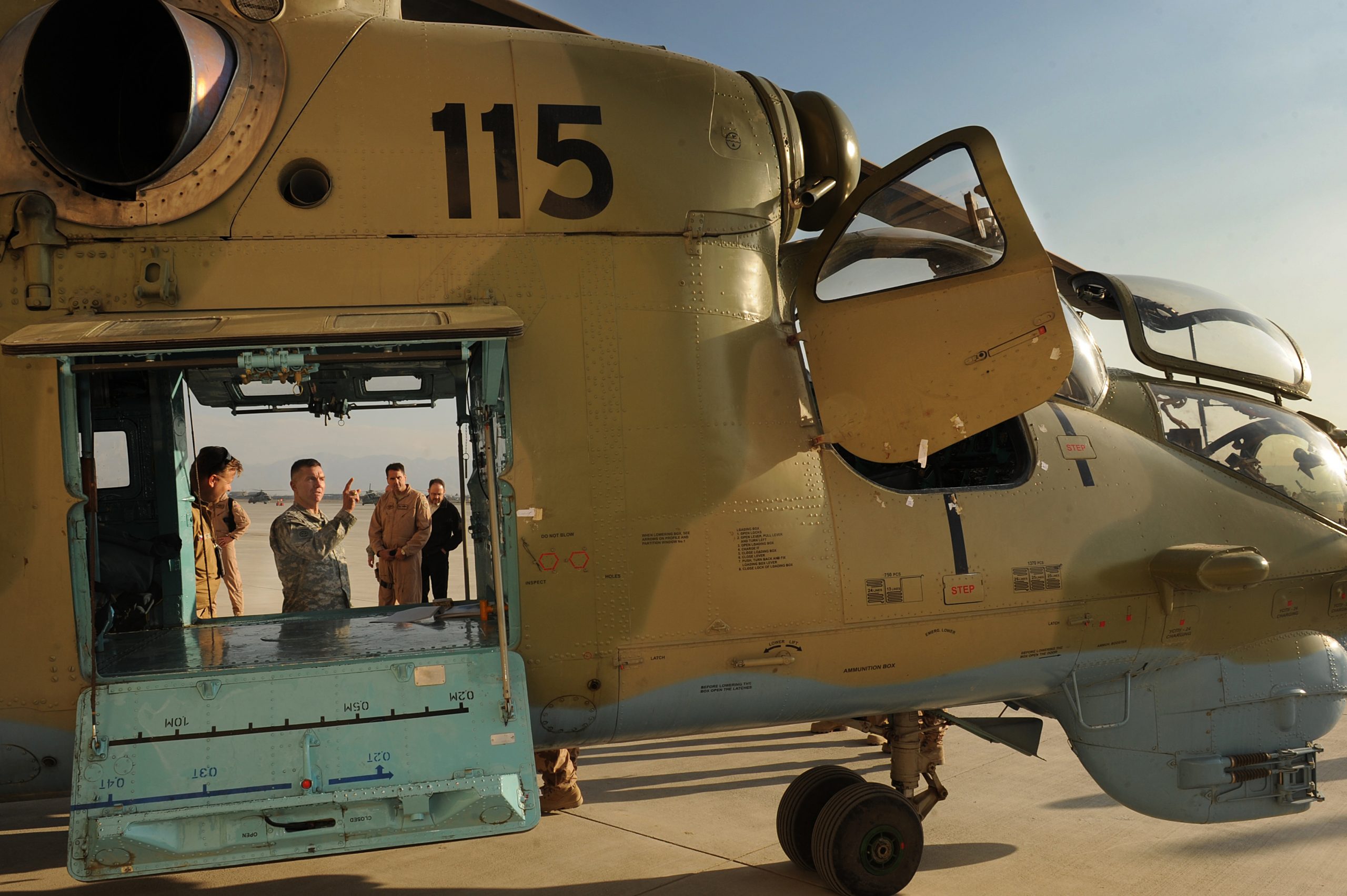
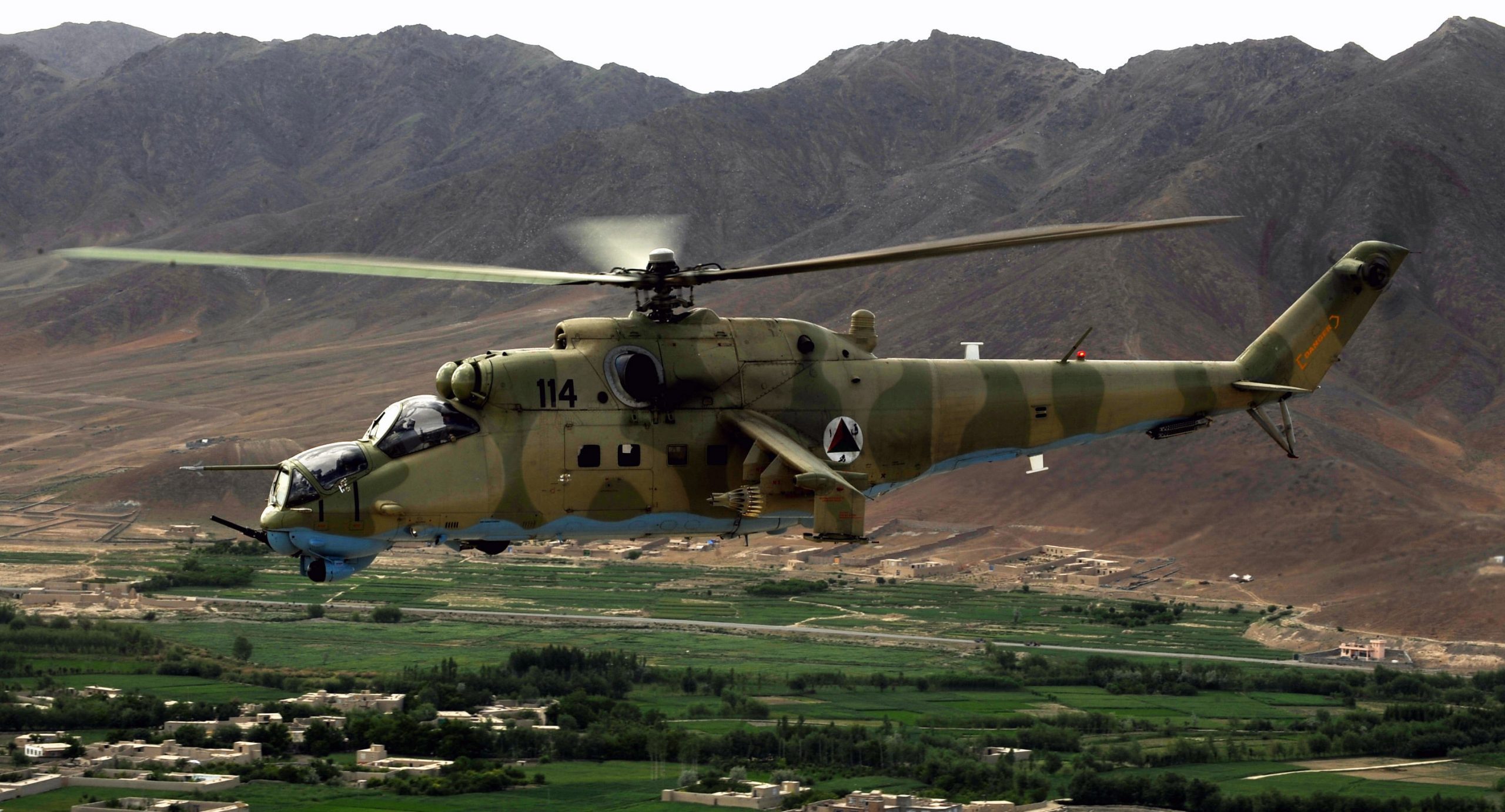

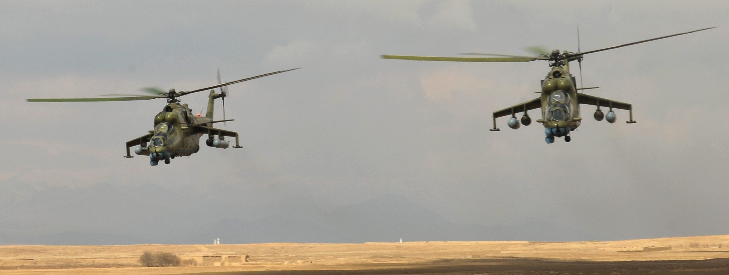

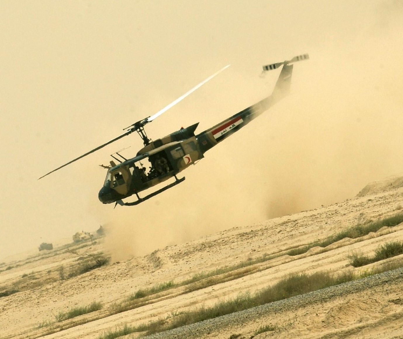
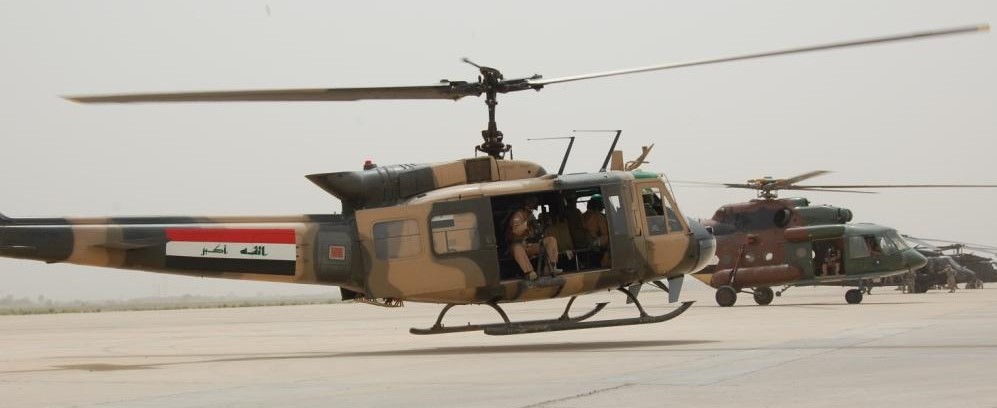
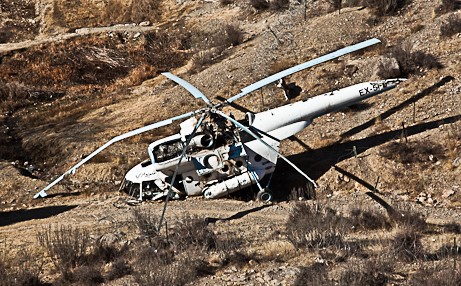
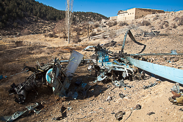
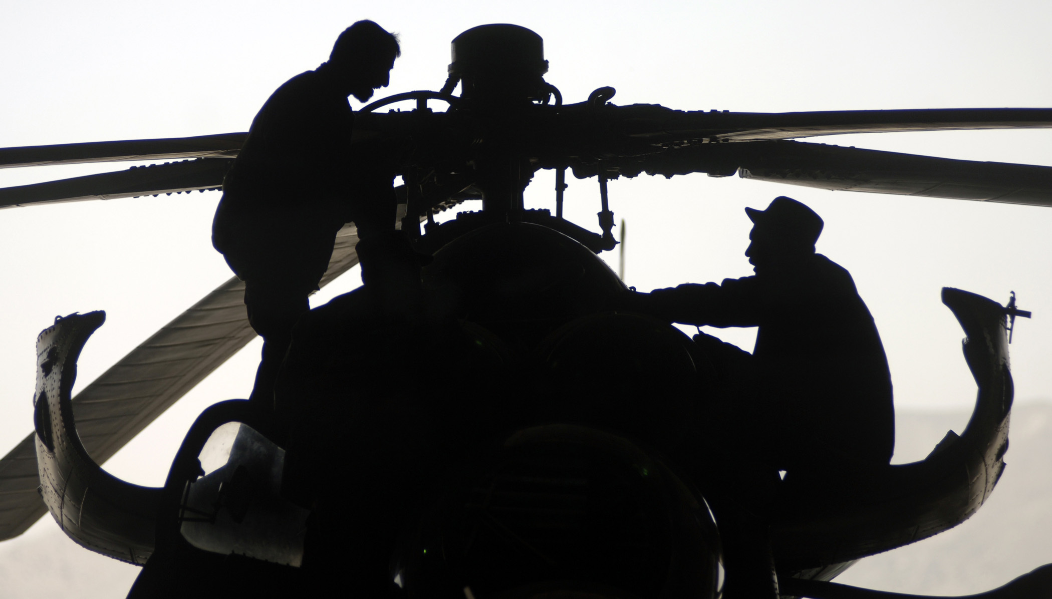
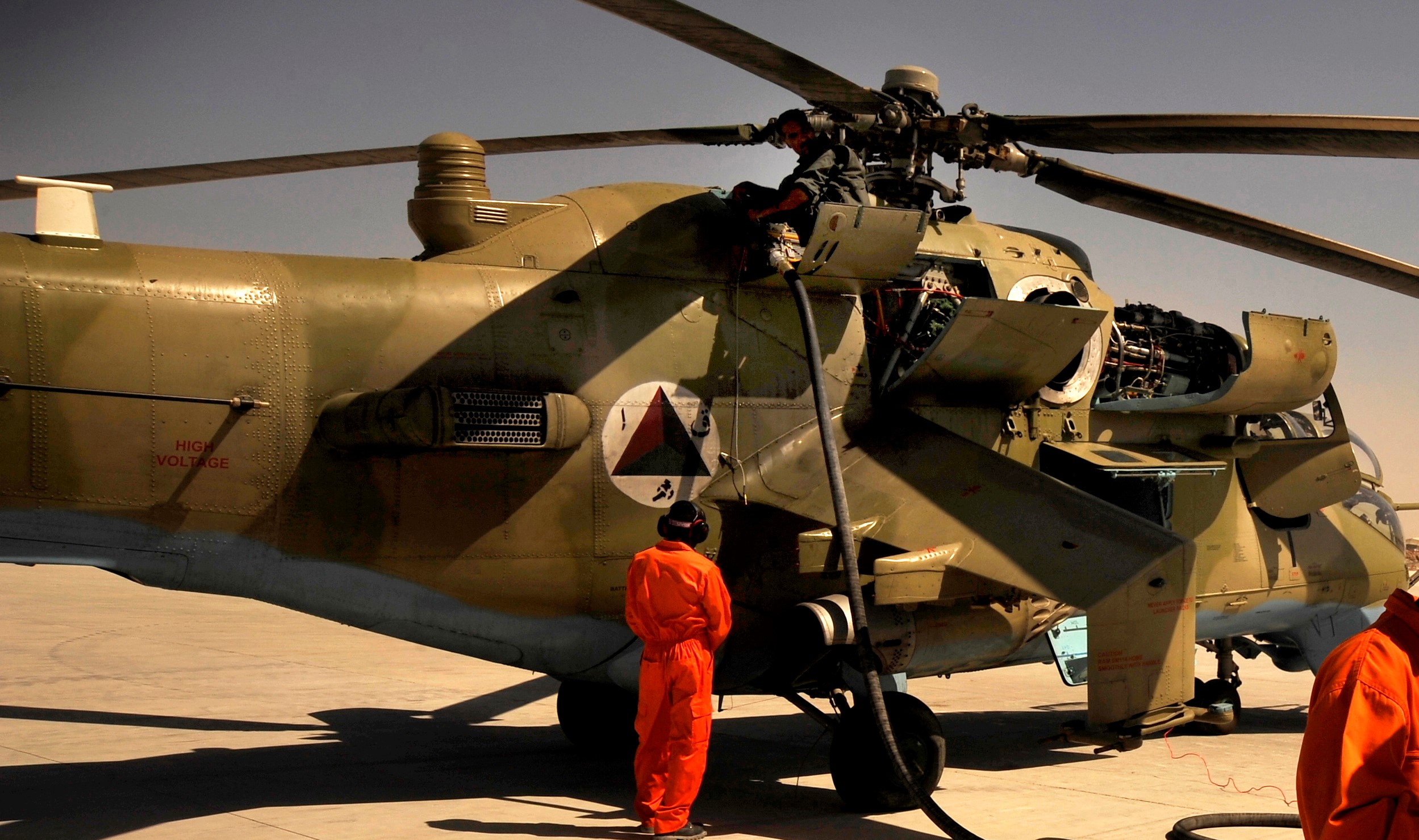
 Sensing an opportunity to make points with the Afghan government, India gifted four refurbished Hinds (originally purchased from Belarus) between 2015 and the end of 2019. The Indian Hinds were denoted as Mi-25s and Mi-24Vs by the Indian news media and even Jane’s Defence Weekly, U.S. news sources refer to the Indian gifted Hinds as Mi-35s.
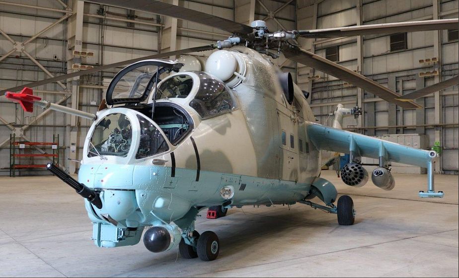


 Polish designed MTLB engineer vehicle known as Opal or TRI, June 2017.
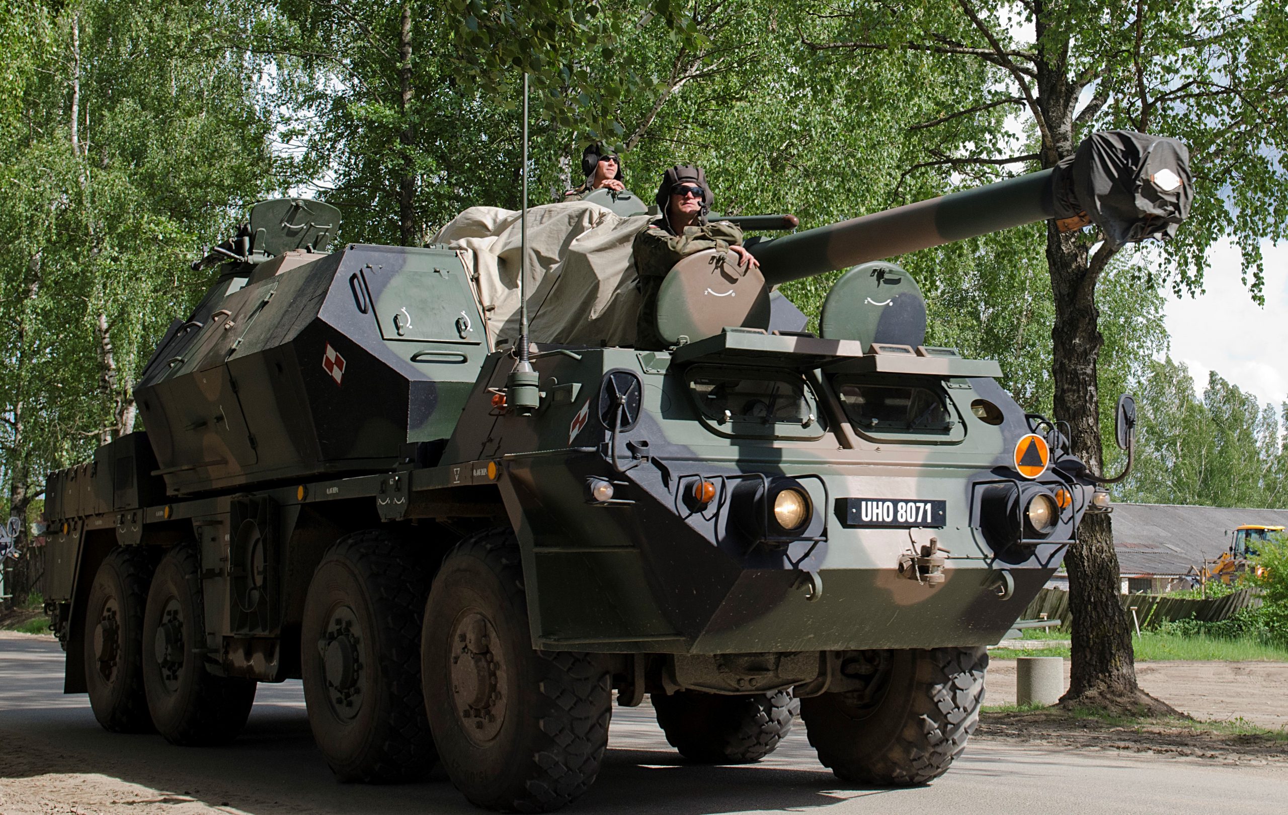
 A PT-91(improved T-72) based WZT-3M recovery vehicle on public display in 2016 (note the Christian priest wearing the tanker helmet).
 WZT-3M, June 2017.


 The PT-91 is Poland’s version of a modernized T-72, this pic was taken in June 2018 during NATO’s Puma 2 Exercise-Saber Strike.