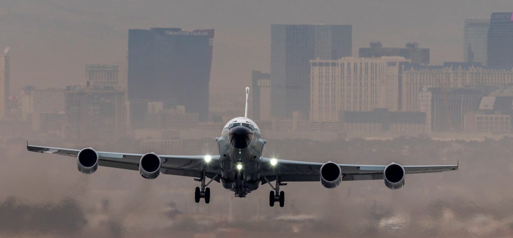
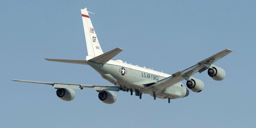
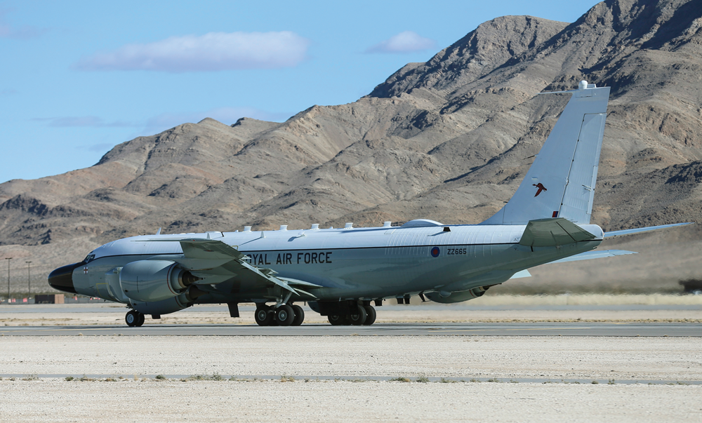
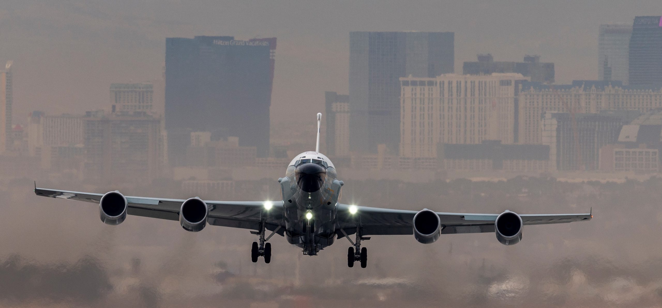
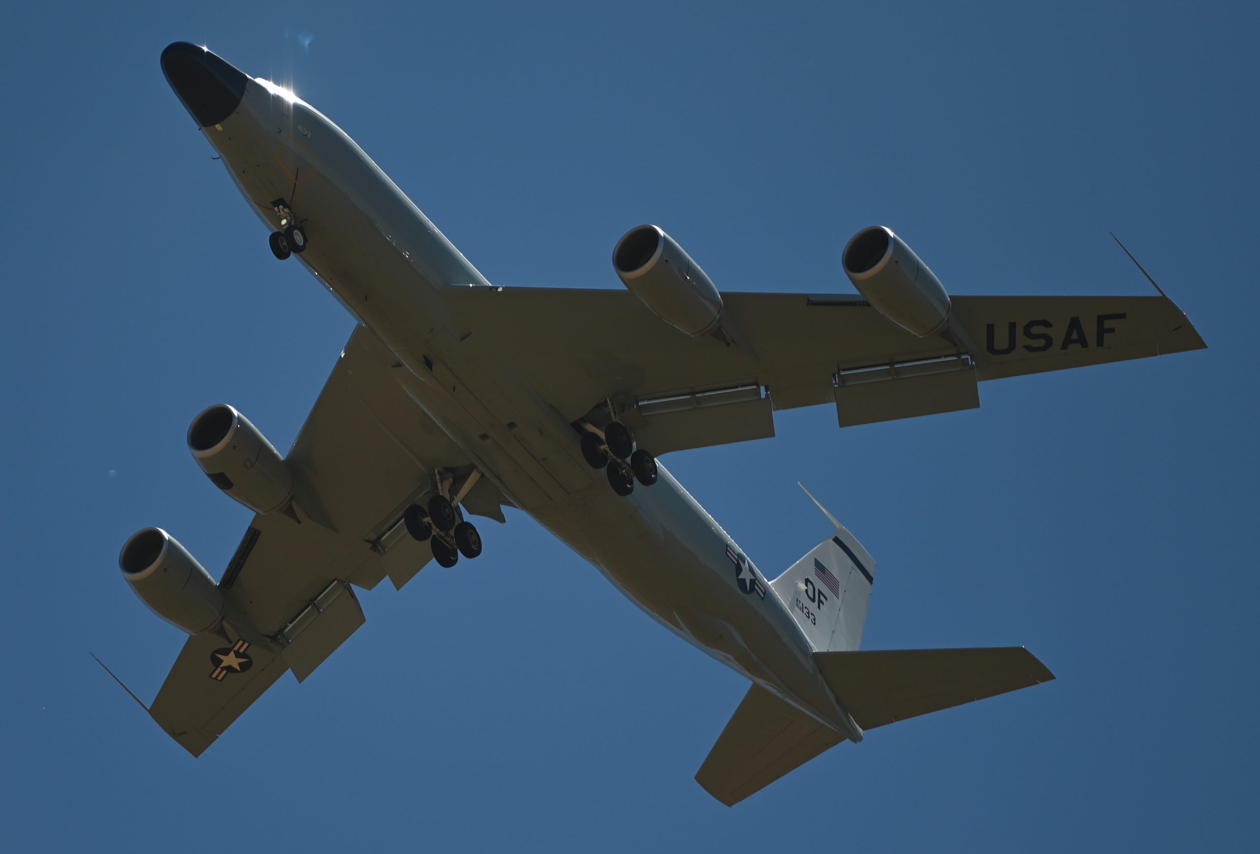
RC-135 Rivet Joint , Las Vegas, Nevada, 07DEC2021. U.S. Air Force photo by William R. Lewis.
Kadena Air Base, Japan, 12MAY2020. U.S. Air Force photo by Staff Sergeant Benjamin Sutton.

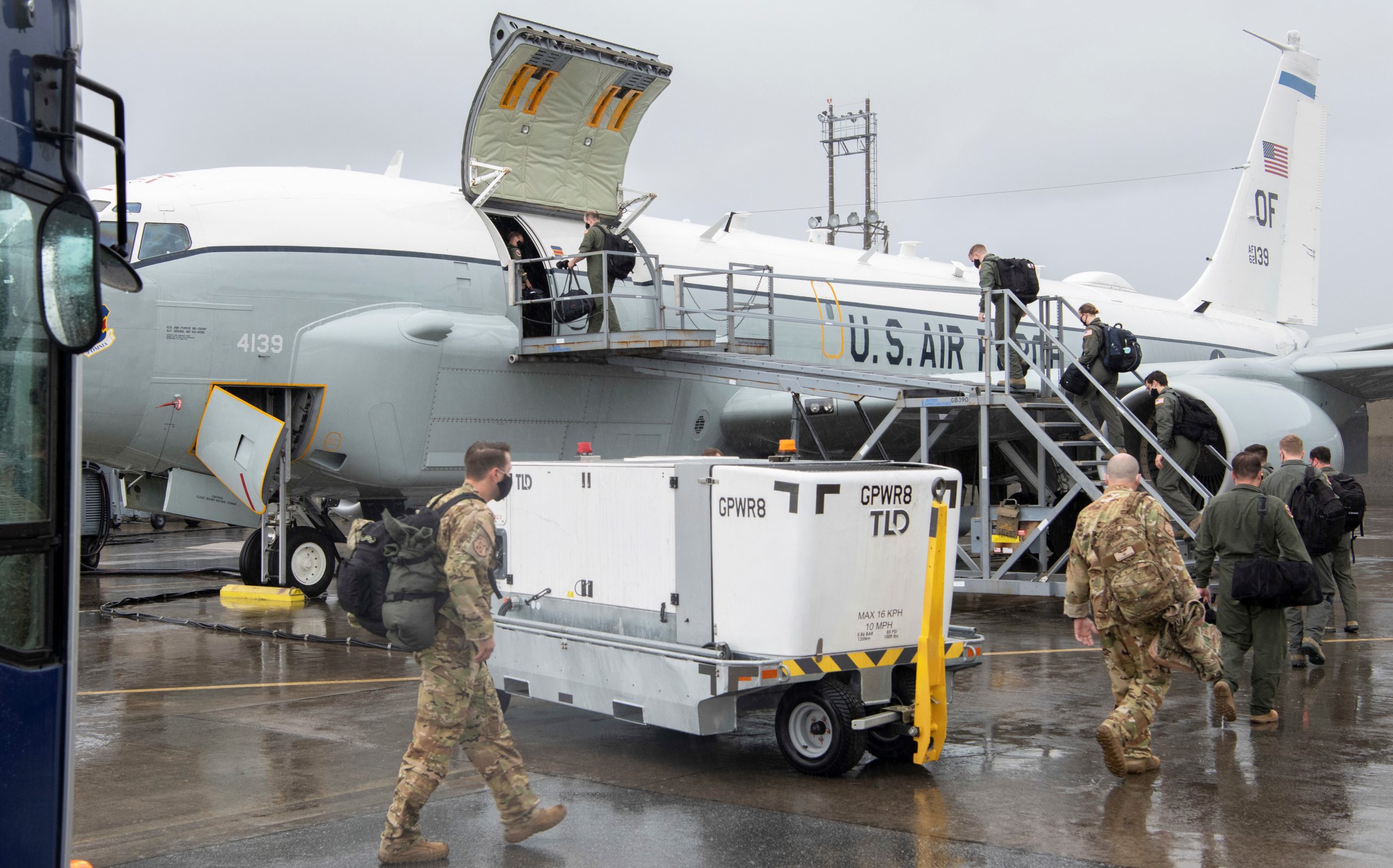
Personnel wearing masks board RC-135V at Kadena Air Base, Japan, 05MAY2020. USAF photo by Senior Airman Rhett Isbell.
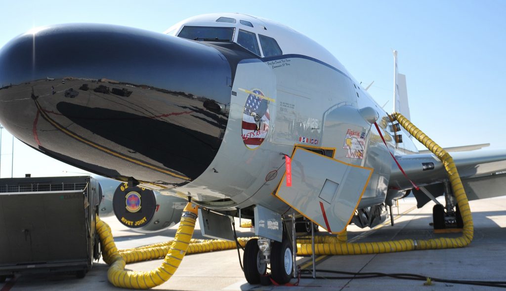
Joint Base San Antonio-Lackland, Texas, 21FEB2020. USAF photo by Manuel Garcia.
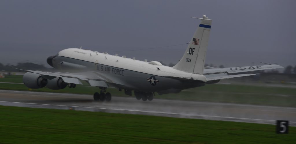
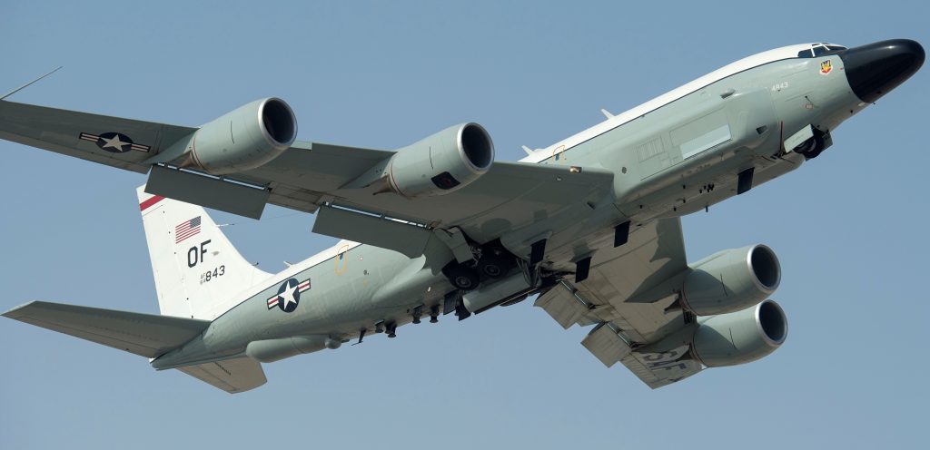
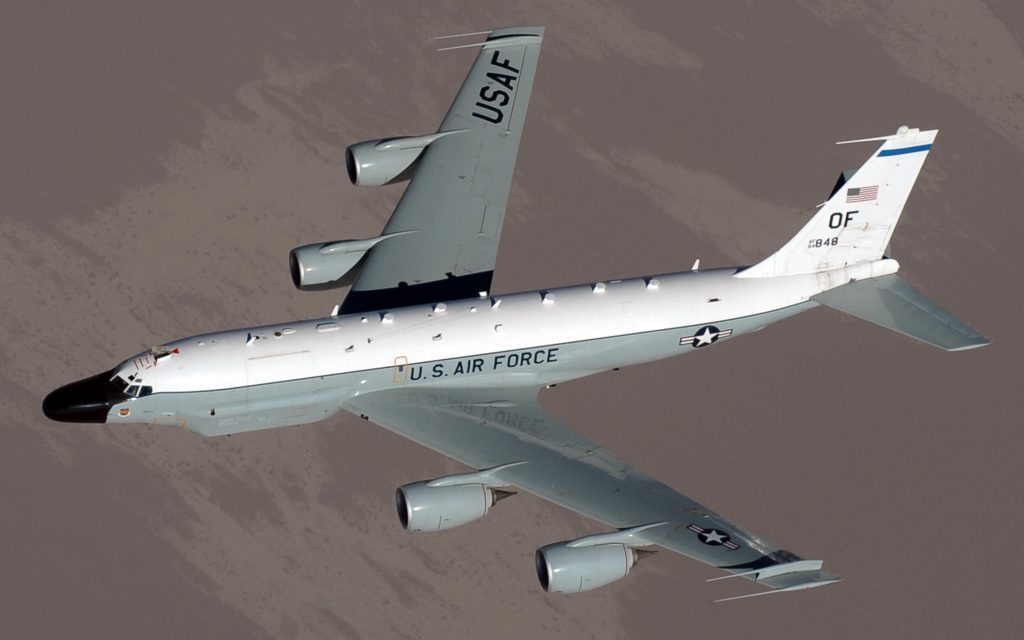
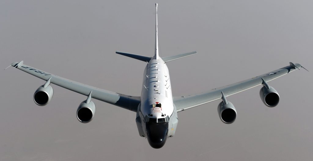
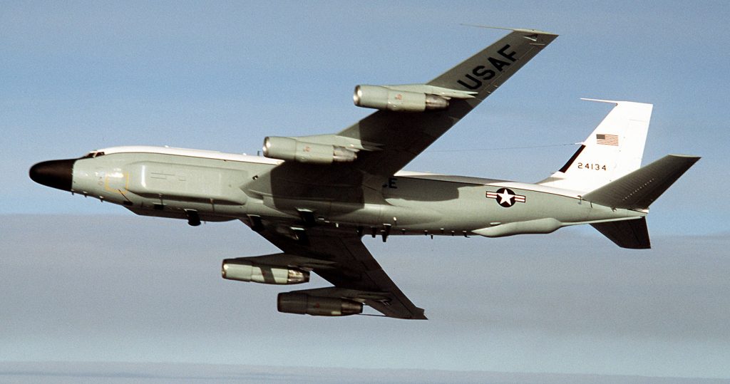
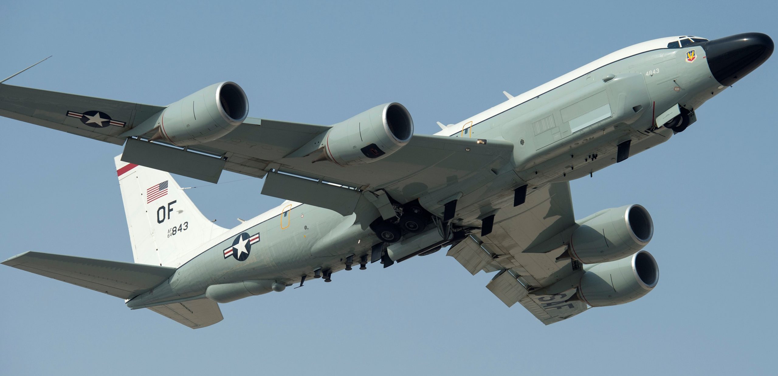
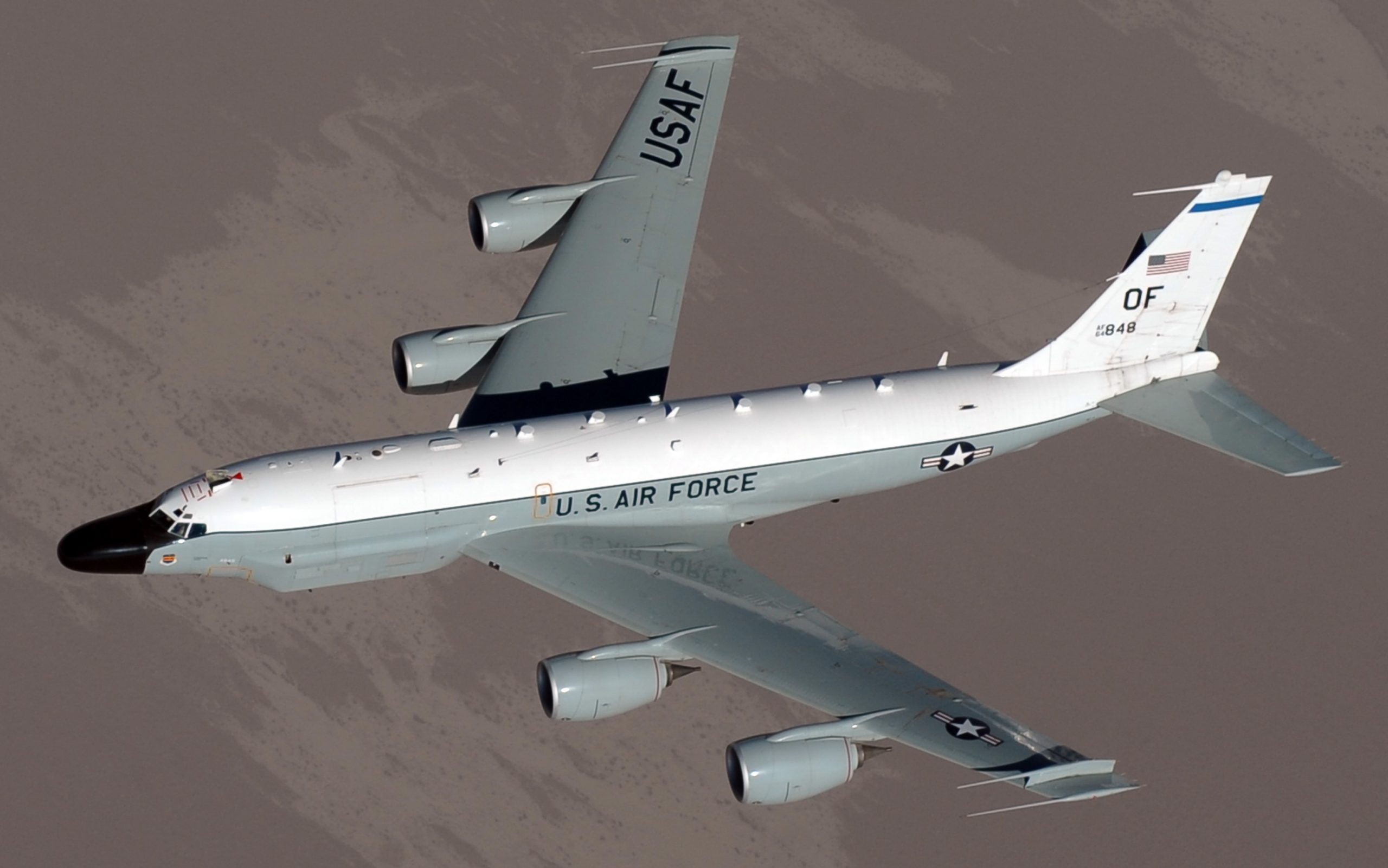
The Boeing RC-135V/W Rivet Joint reconnaissance aircraft are the most recent members of the RC-135 family, which can be traced back to 1964. The difference between the ‘V’ and ‘W’ variants depends upon which C-135 was upgraded/modified to Rivet Joint standard; RC-135Vs are upgraded RC-135Cs, while RC-135Ws are modified C-135Bs.
USAF photo by Manuel Garcia, 21FEB2020.
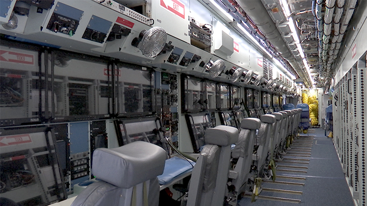
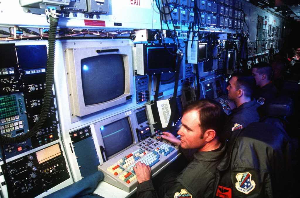
It provides near-real-time on-scene intelligence collection, primarily by detecting, identifying and geolocating signals throughout the electromagnetic spectrum.
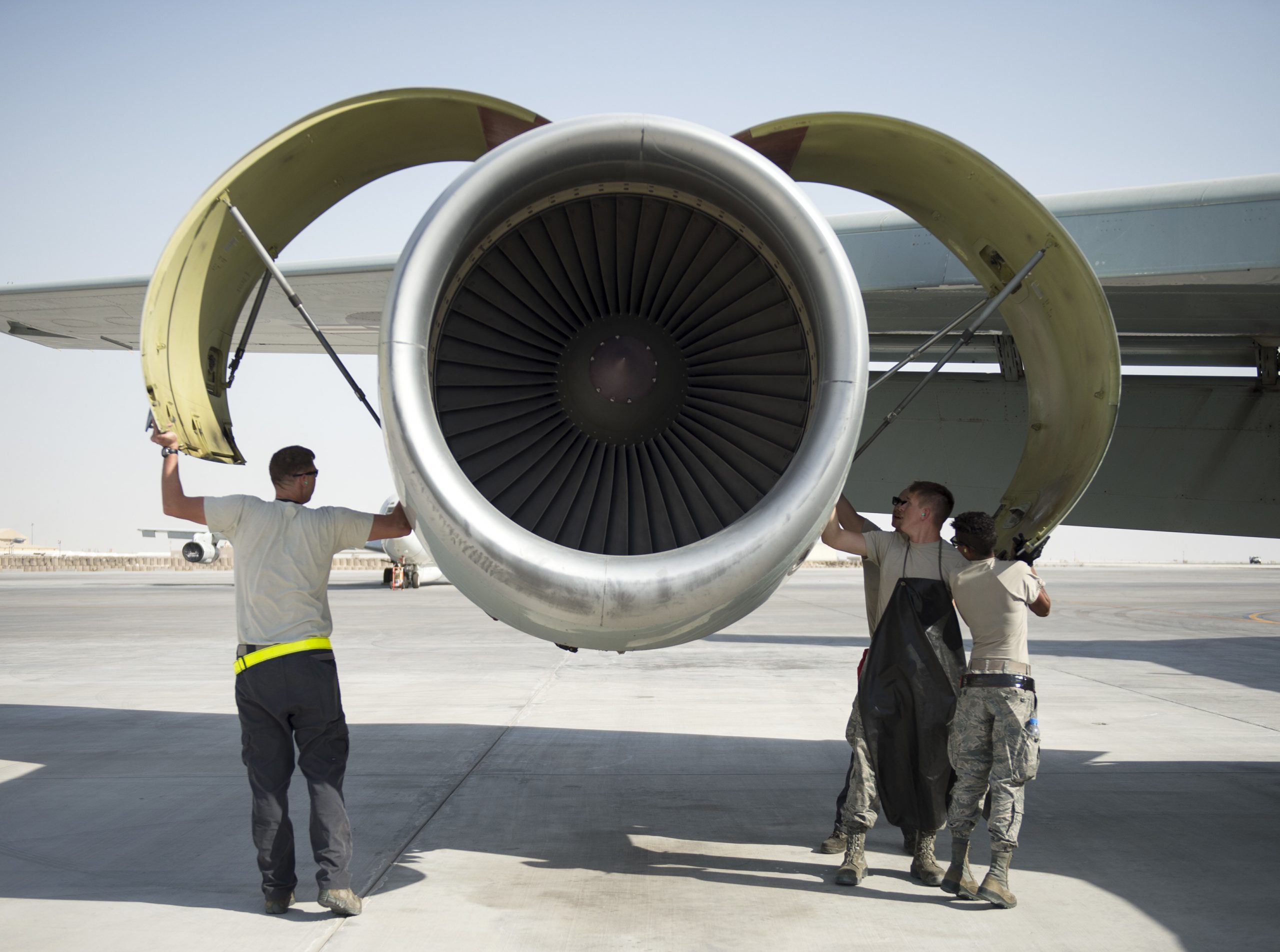
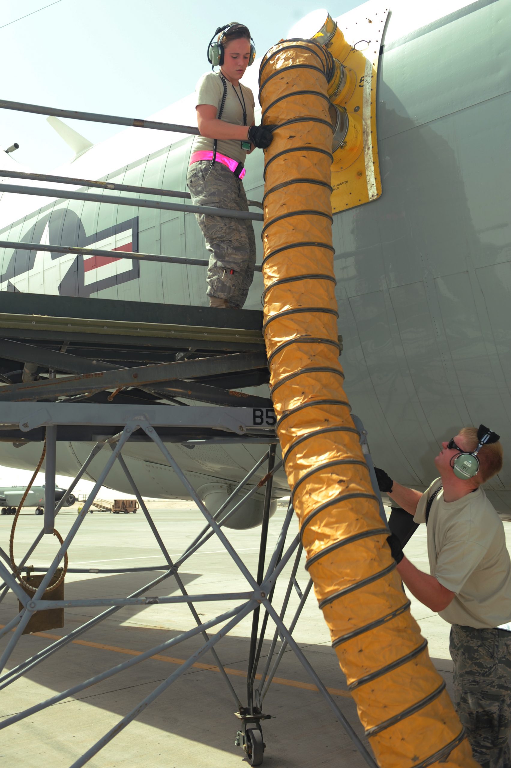
Al Udeid Air Base, Qatar, 28JUL2017. USAF photo by Technical Sergeant Amy Lovgren.
Al Udeid Air Base, Qatar, 28JUL2017. Photo by Technical Sergeant Amy Lovgren.
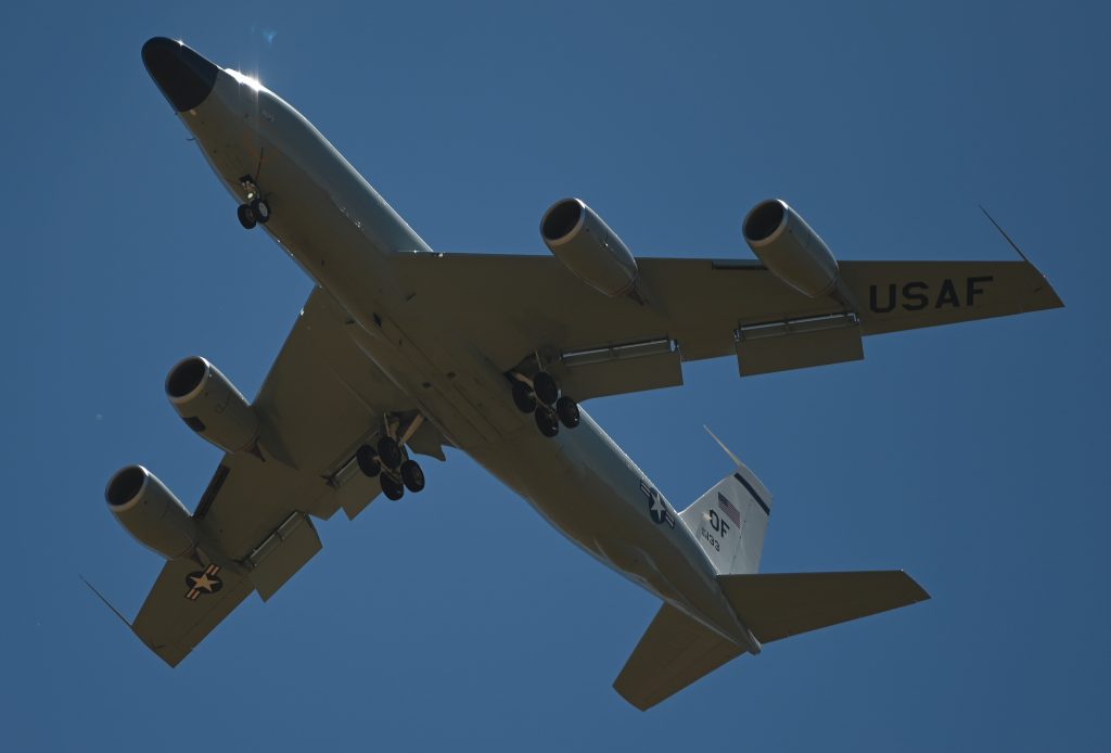
It can carry a crew of more than 30 people, and is powered by four CFM-56 turbofans.

Al Udeid Air Base, Qatar, 27JUL2017. USAF photo by Technical Sergeant Amy Lovgren.
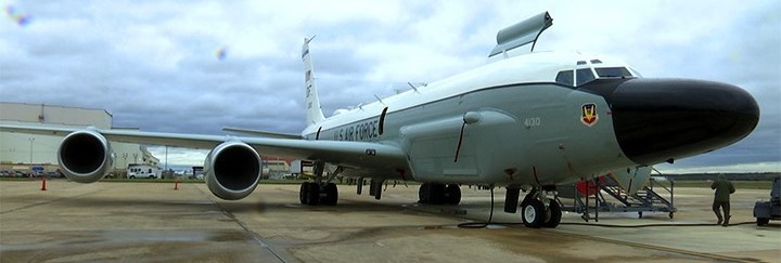
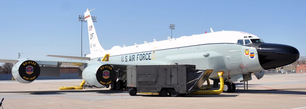
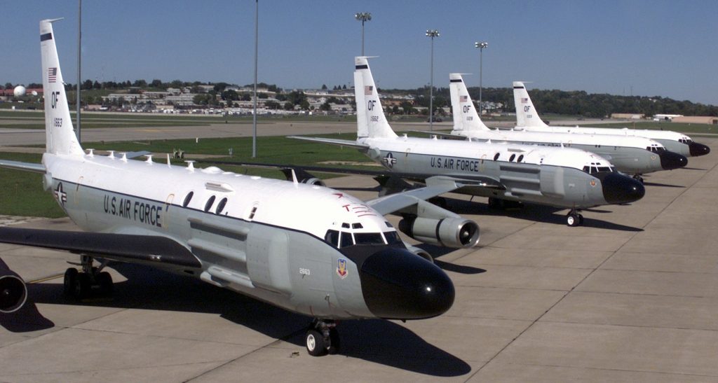
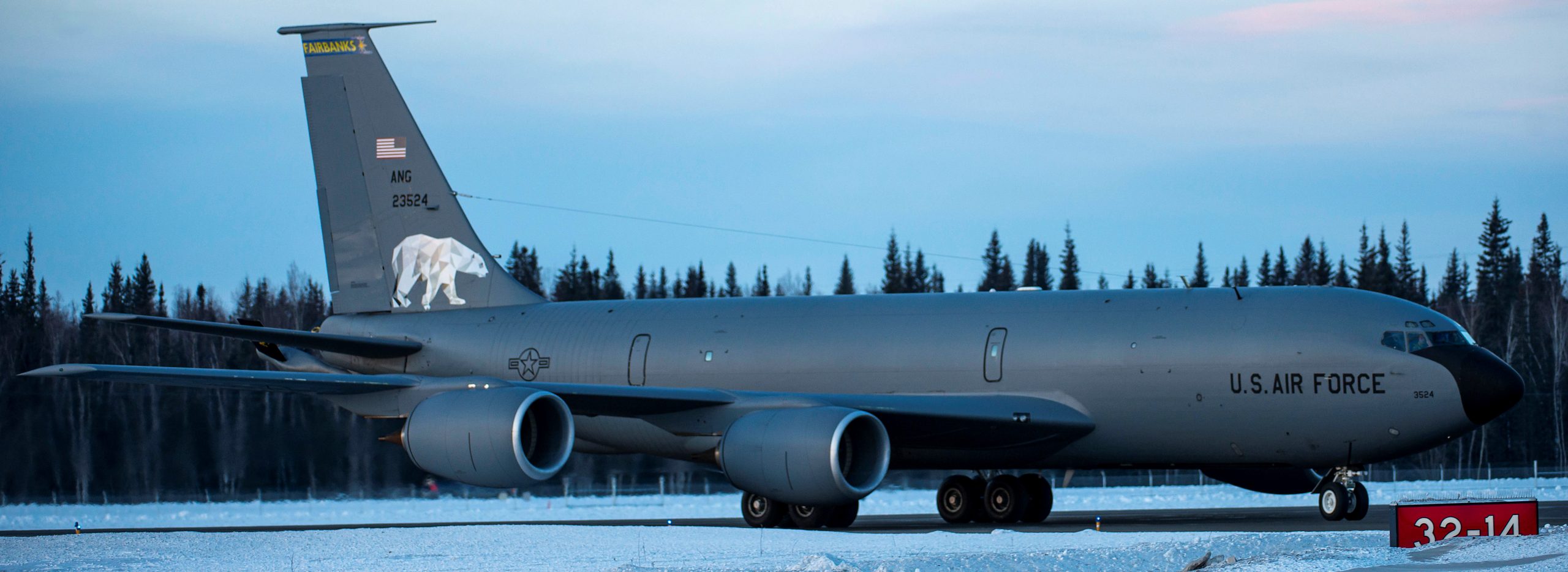
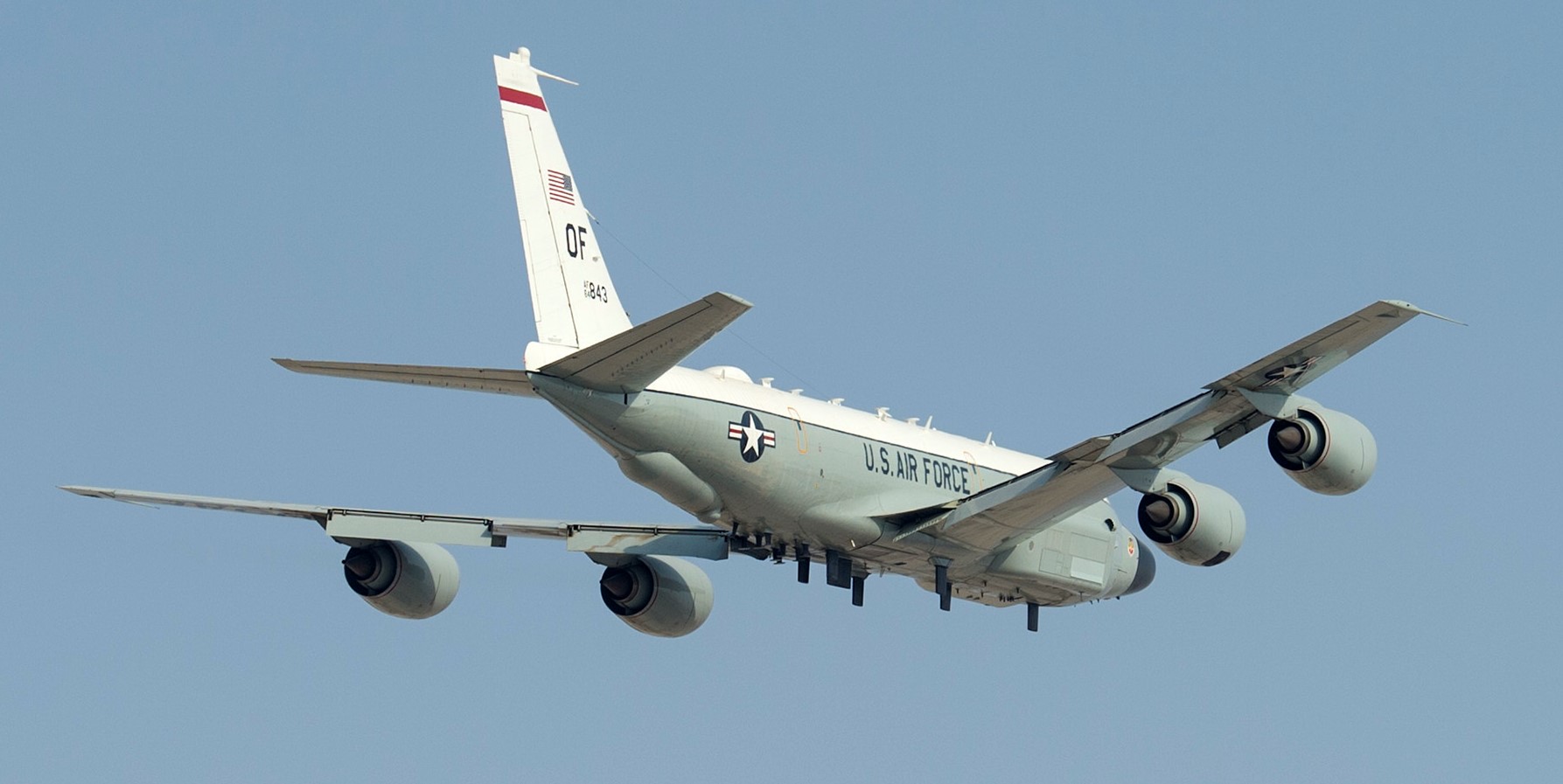
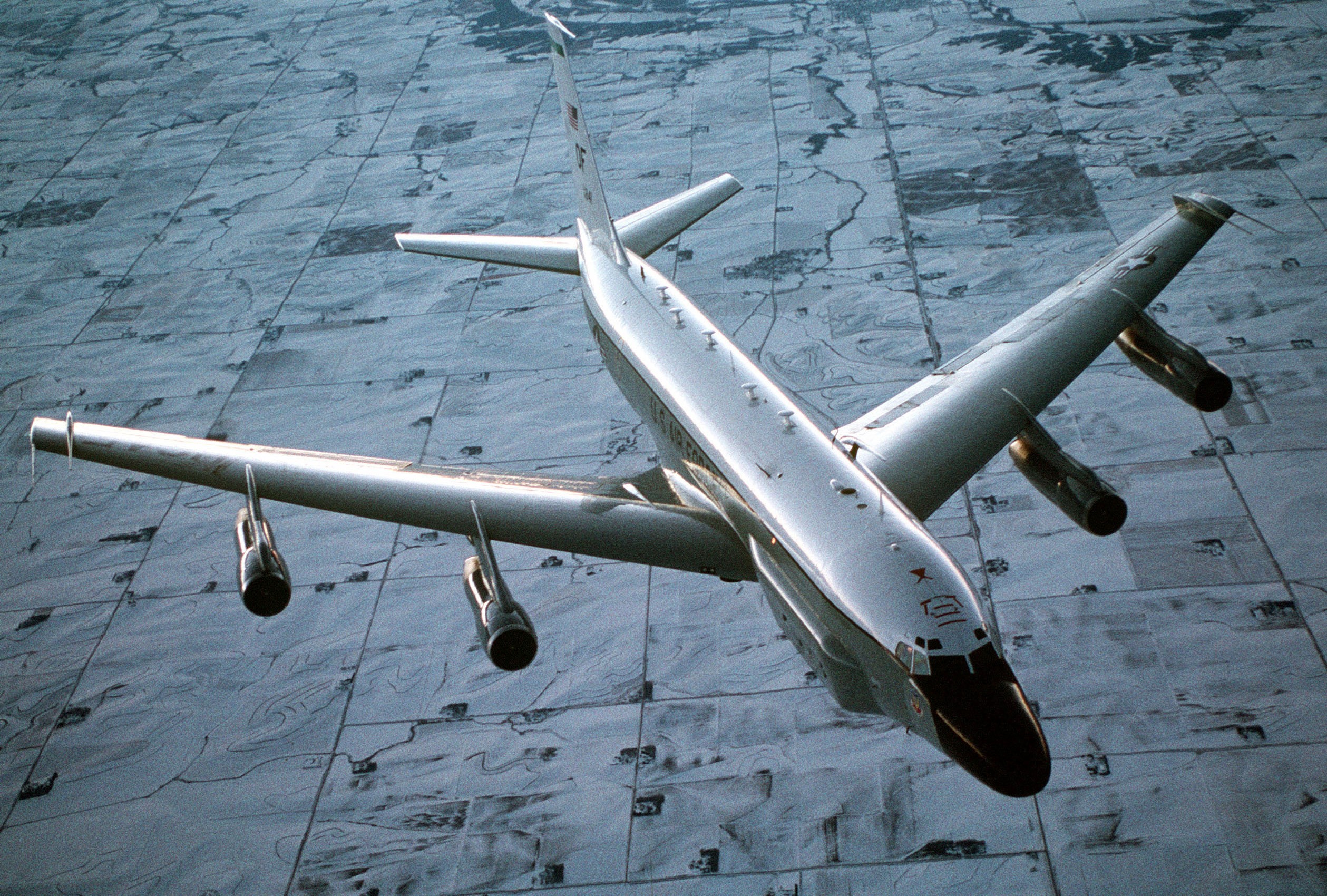
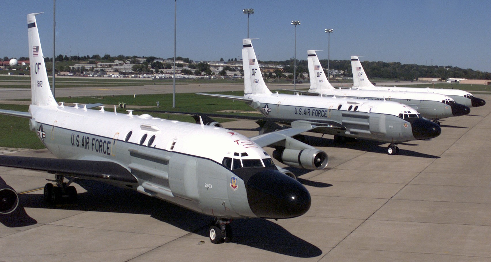
Currently, U.S. Air Force Rivet Joints are flown by the 55th Wing, based out of Offutt Air Force Base (AFB), Nebraska.
Offutt AFB, Nebraska, 13MAR2012. USAF photo by Jeffrey Gates.
Time lapse video by Senior Airman Jacob Skovo-Lane, How to Wash your Rivet Joint, October 2018:
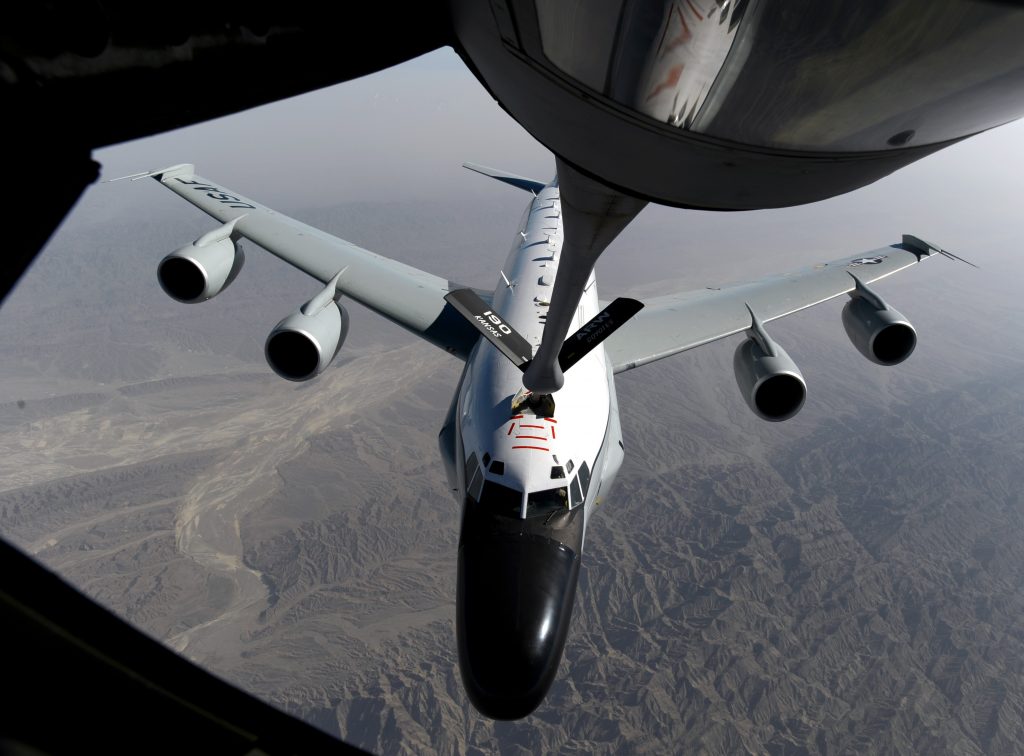
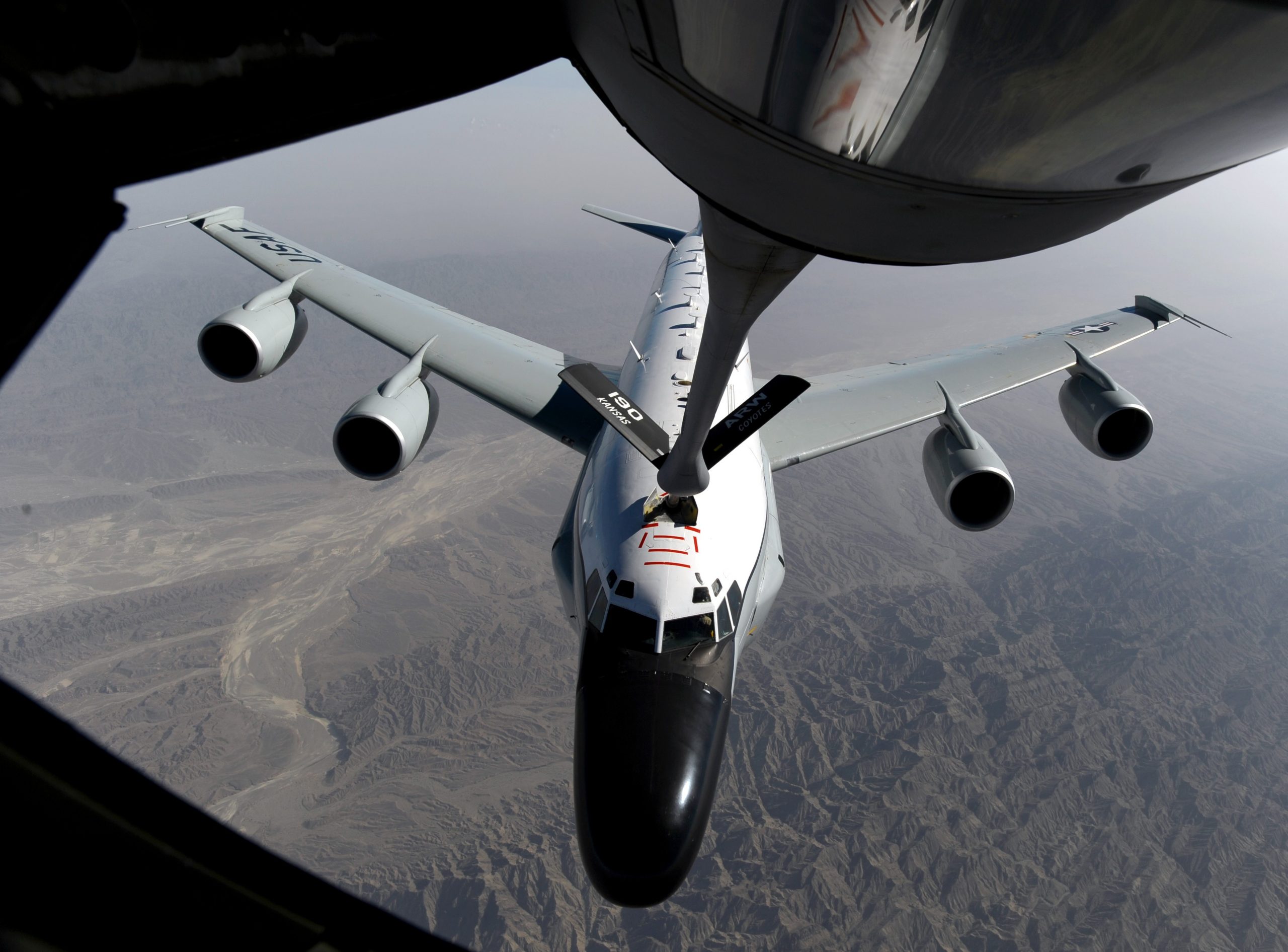
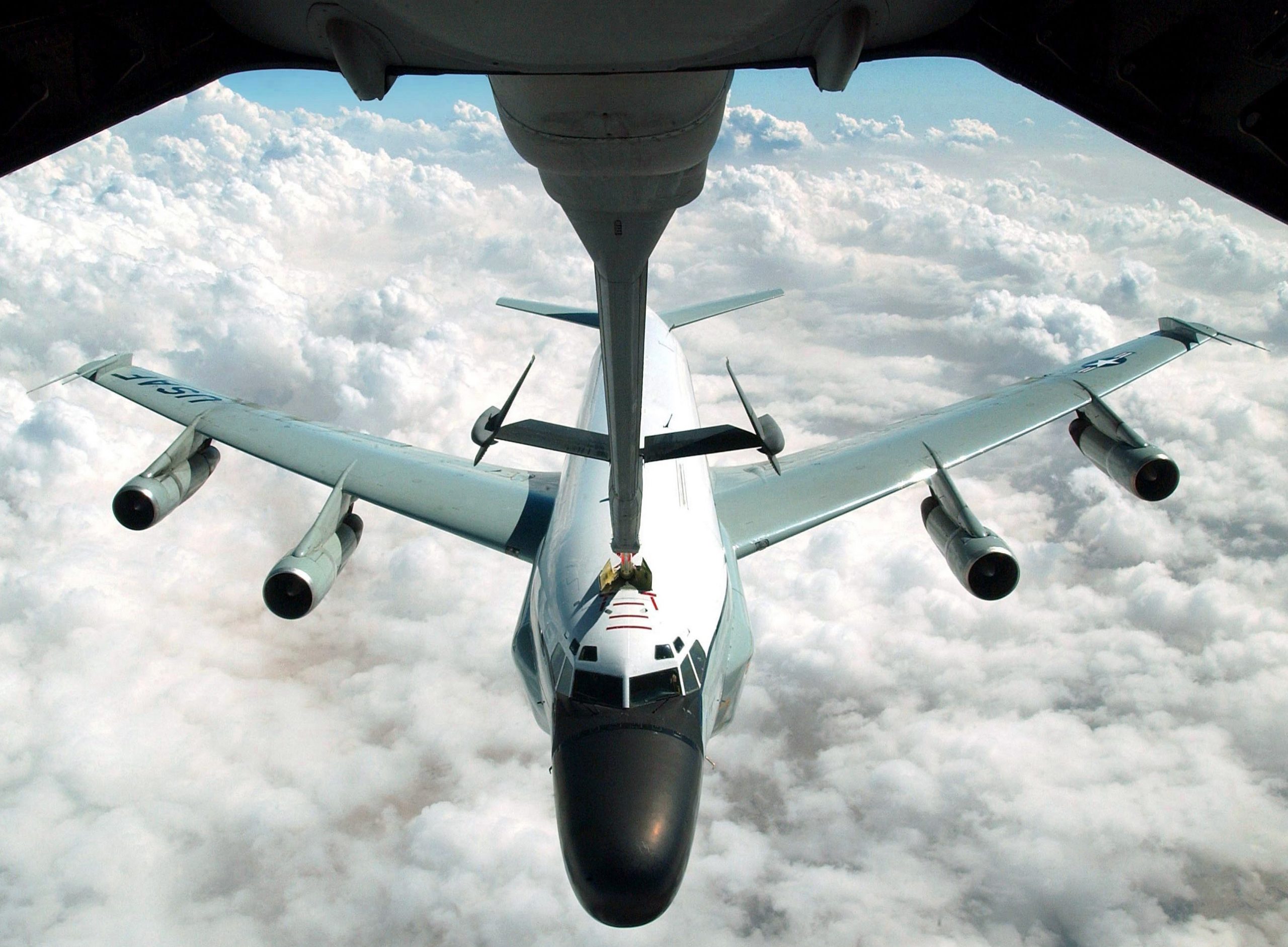
Video by Senior Airman Joshua Hoskins, Michigan Air National Guard re-fuels Rivet Joint over Afghanistan, January 2017:
Offutt AFB, 13MAR2012. USAF photo by Jeffrey Gates.
Over Afghanistan, 19JUN2011. USAF photo by Master Sergeant William Greer.
Over Afghanistan, 19JUN2011. USAF photo by Master Sergeant William Greer.
Over Afghanistan, 19JUN2011. USAF photo by Master Sergeant William Greer.
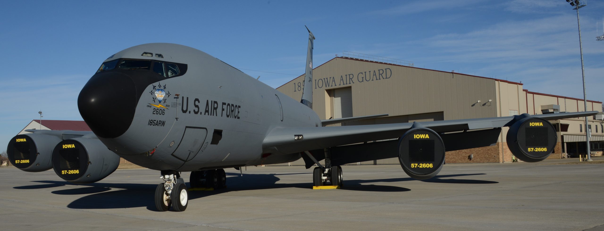
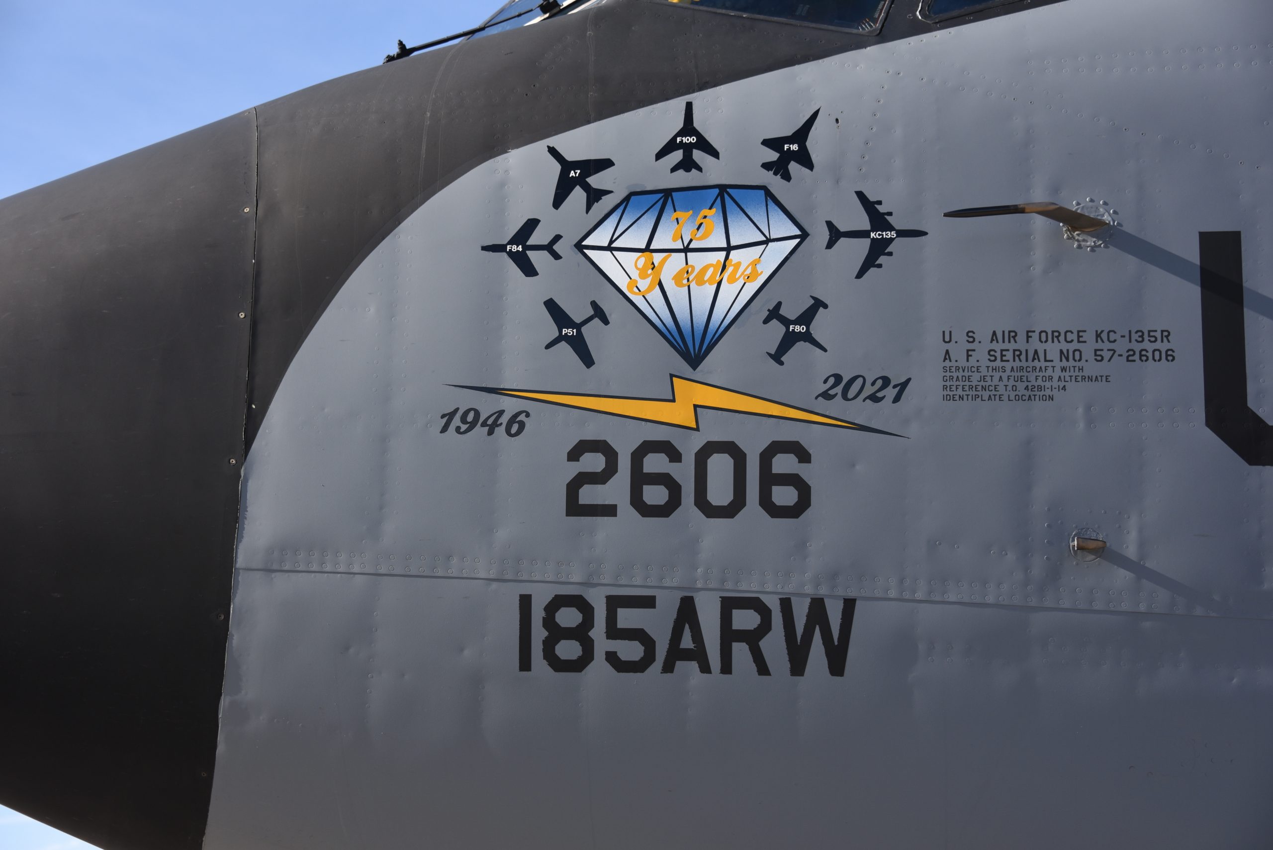
In August 2010, the USAF celebrated 20 years of Rivet Joint operations, with aircraft that are as much as 50 years old:
During the pandemic of 2020, believe it or not a mask was created for the nose of the RC-135. It is nicknamed The Mule Mask. Video interview of mask creator Technical Sergeant Kristen Horwith by Staff Sergeant Lexie West, 11AUG2020:
Video by (then) Senior Airmen Lexie West, USAF RC-135 at RAF Mildenhall, United Kingdom, November 2017:

RAF RC-135W Airseeker, Offutt AFB, Nebraska, 02MAY2018. USAF photo by Senior Airman Jacob Skovo-Lane.
RAF RC-135W Airseeker, Offutt AFB, Nebraska, 02MAY2018. USAF photo by Senior Airman Jacob Skovo-Lane.
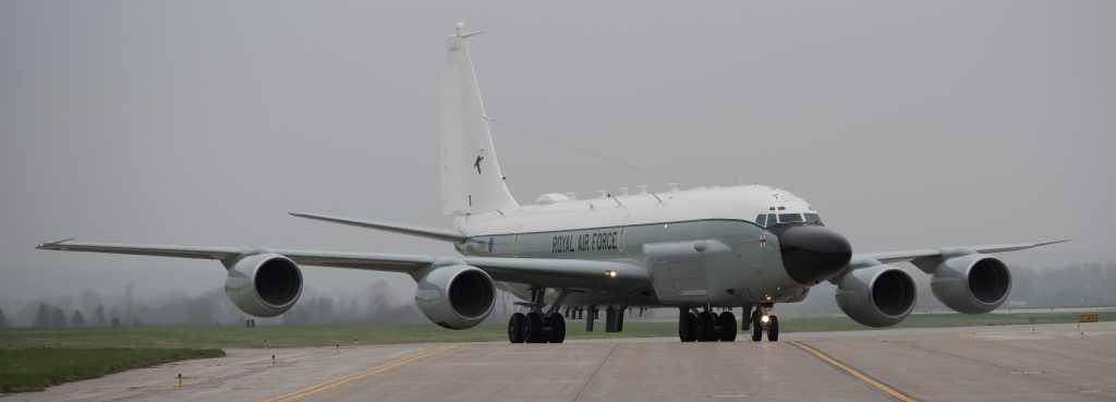
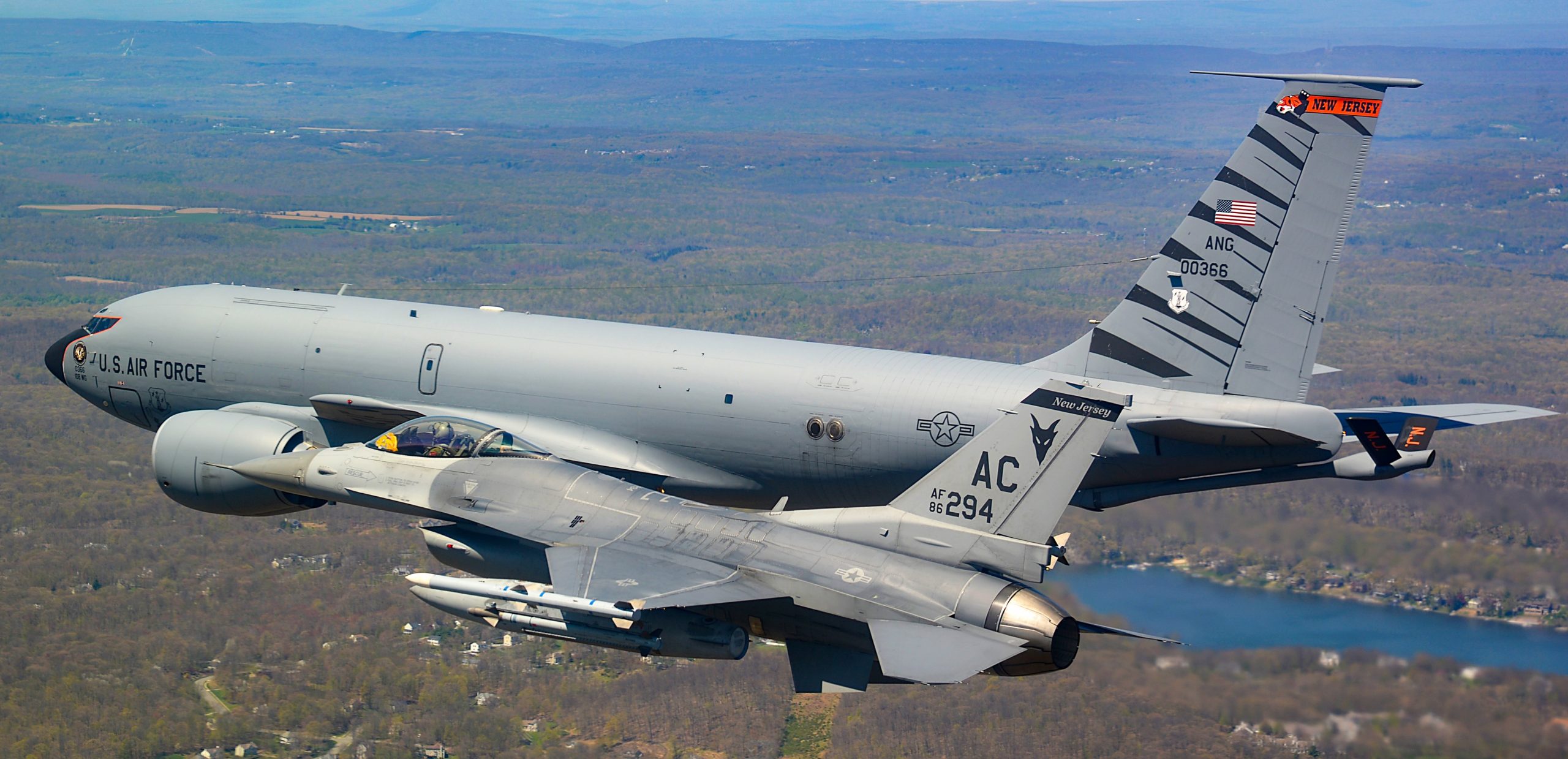
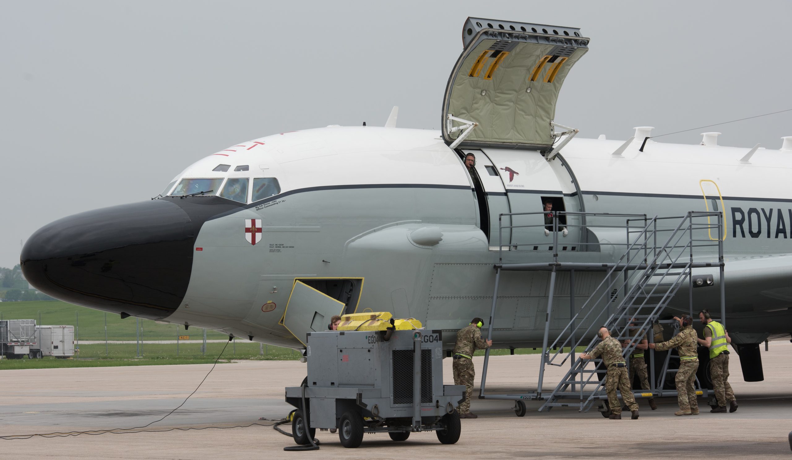
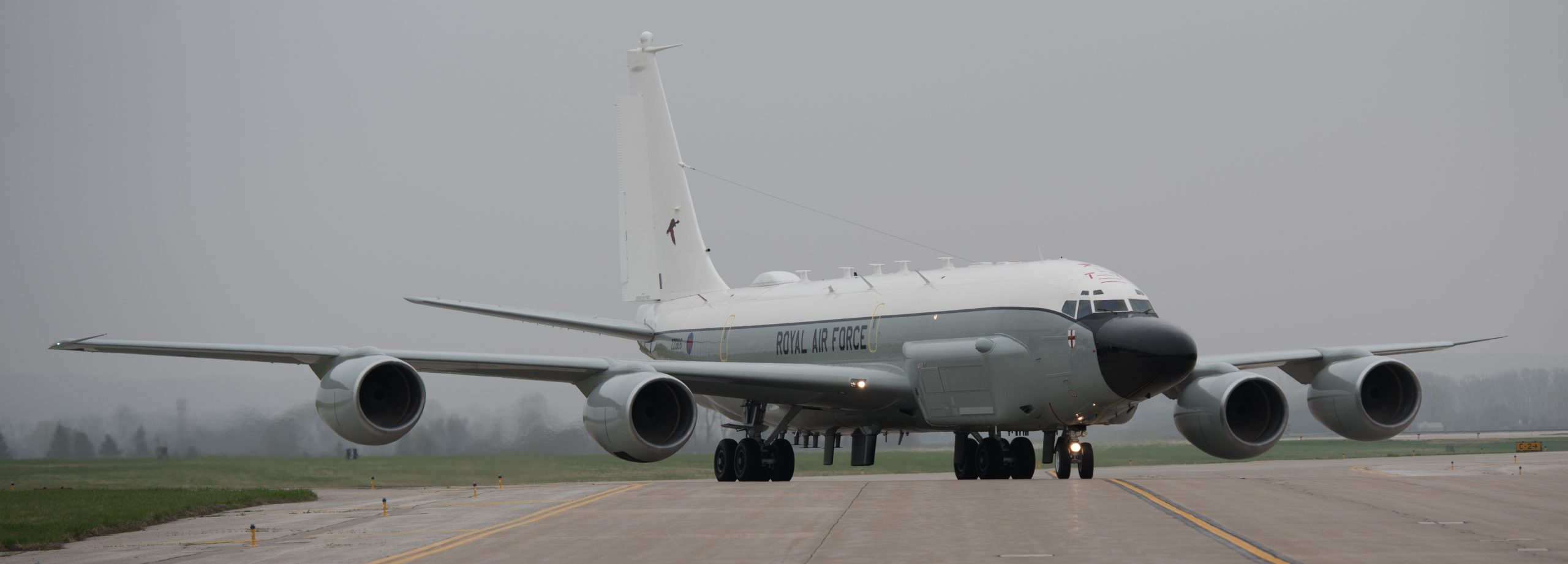
For the Commonwealth of Nations (formerly British Commonwealth of Nations, formerly British Empire) member United Kingdom, in 2011 the RC-135W was chosen as the replacement for the Royal Air Force’s (RAF) BAe Nimrod R Mark 1. In November 2013 the RAF received it’s first RC-135W, flying it’s first mission in May 2014. The official British name for the RC-135W is Airseeker.
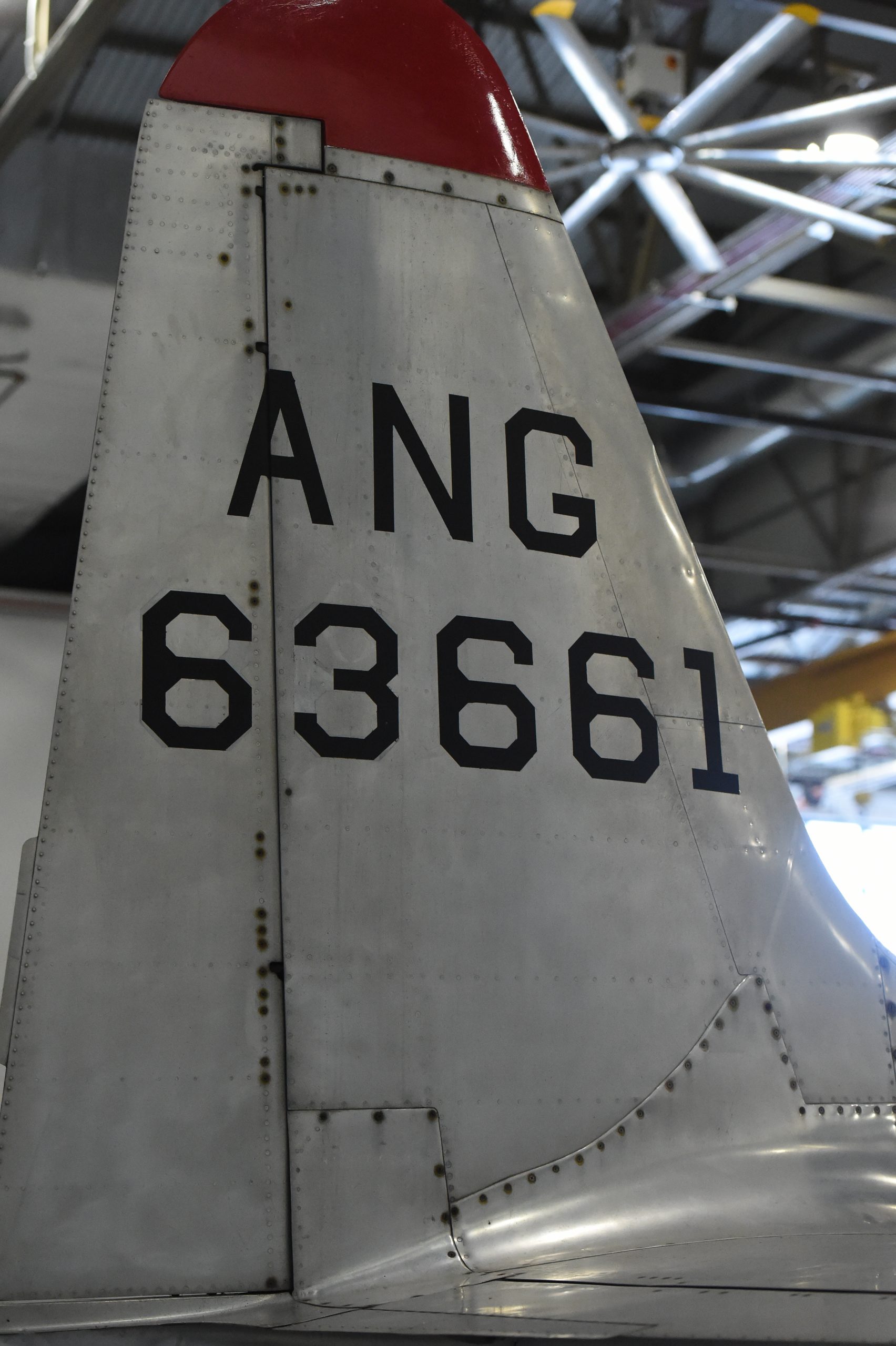
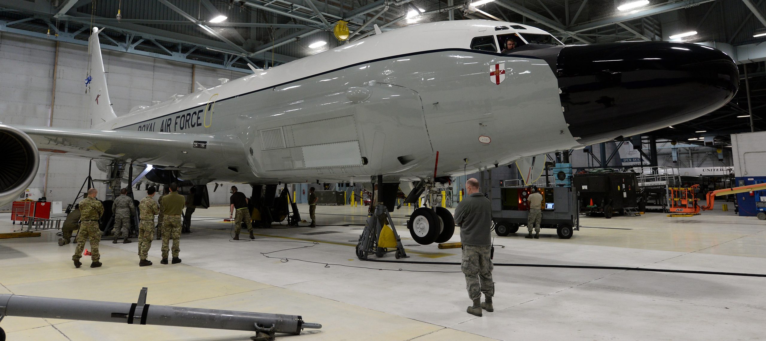
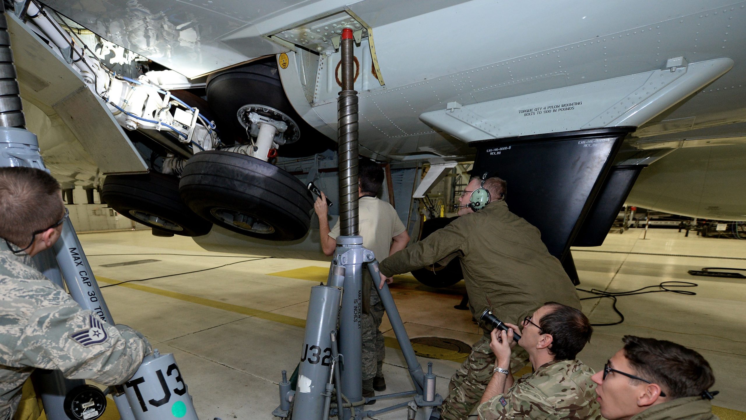
12FEB2017, Airseeker undergoing landing gear inspection, Offutt AFB. USAF photo by Delanie Stafford.
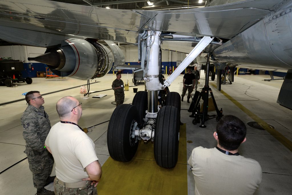
12FEB2017, Airseeker undergoing landing gear inspection, Offutt AFB. USAF photo by Delanie Stafford.
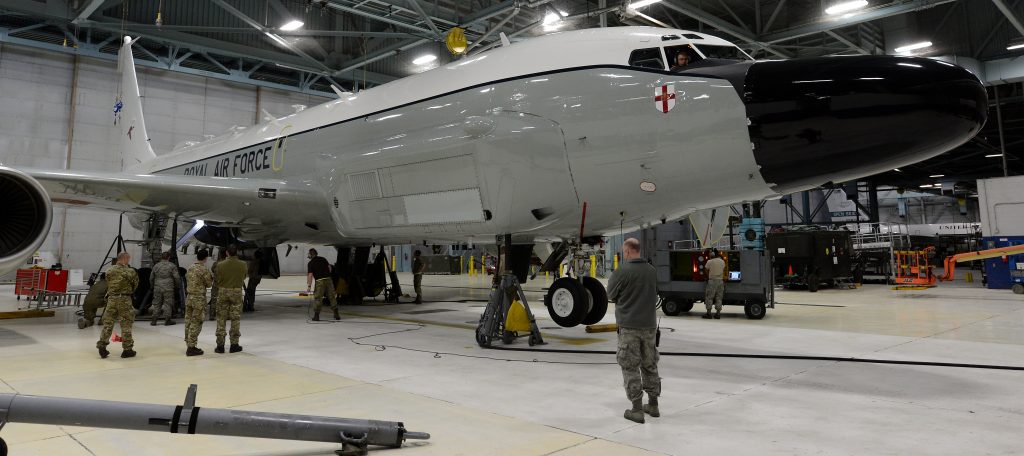
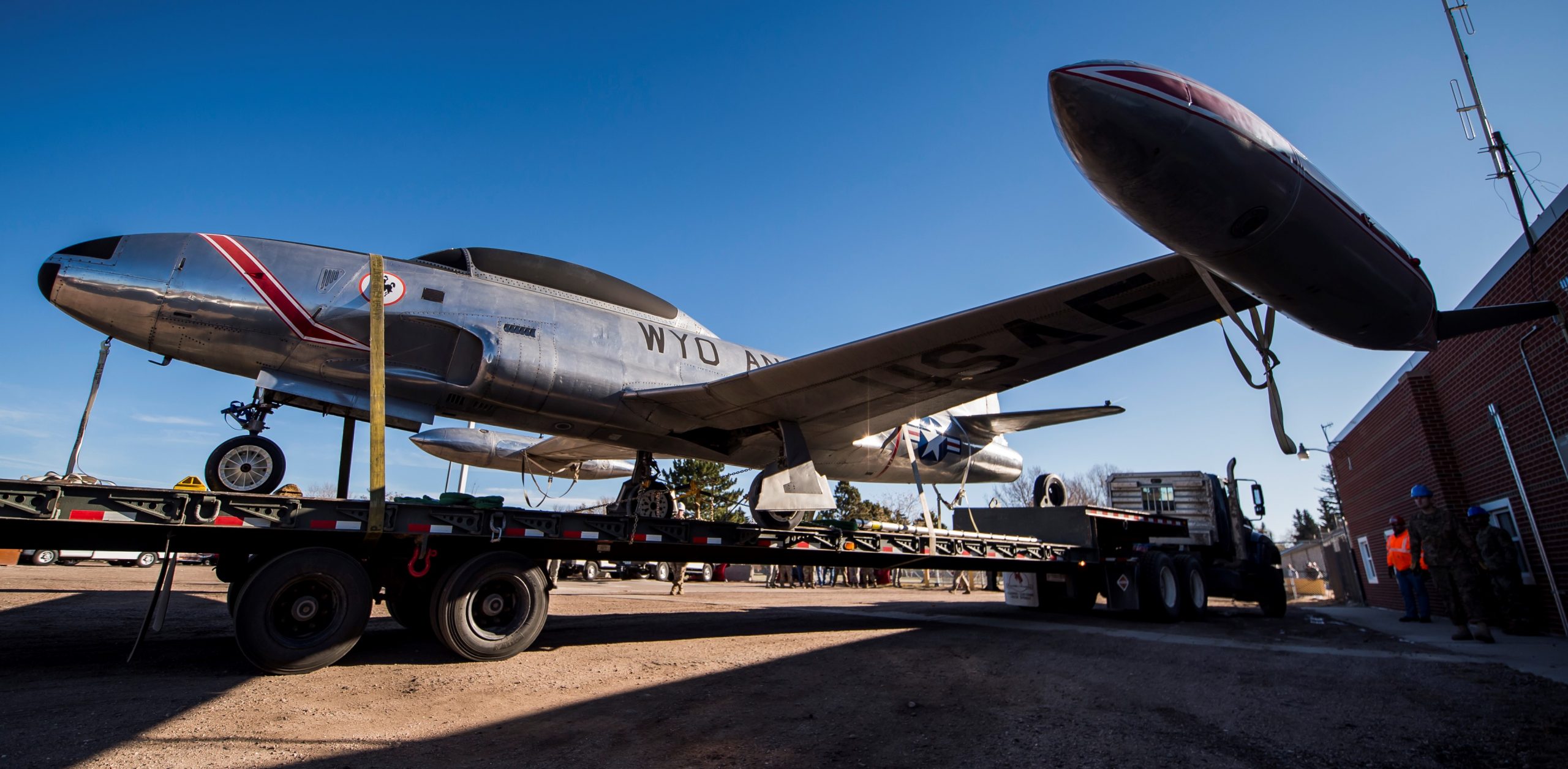
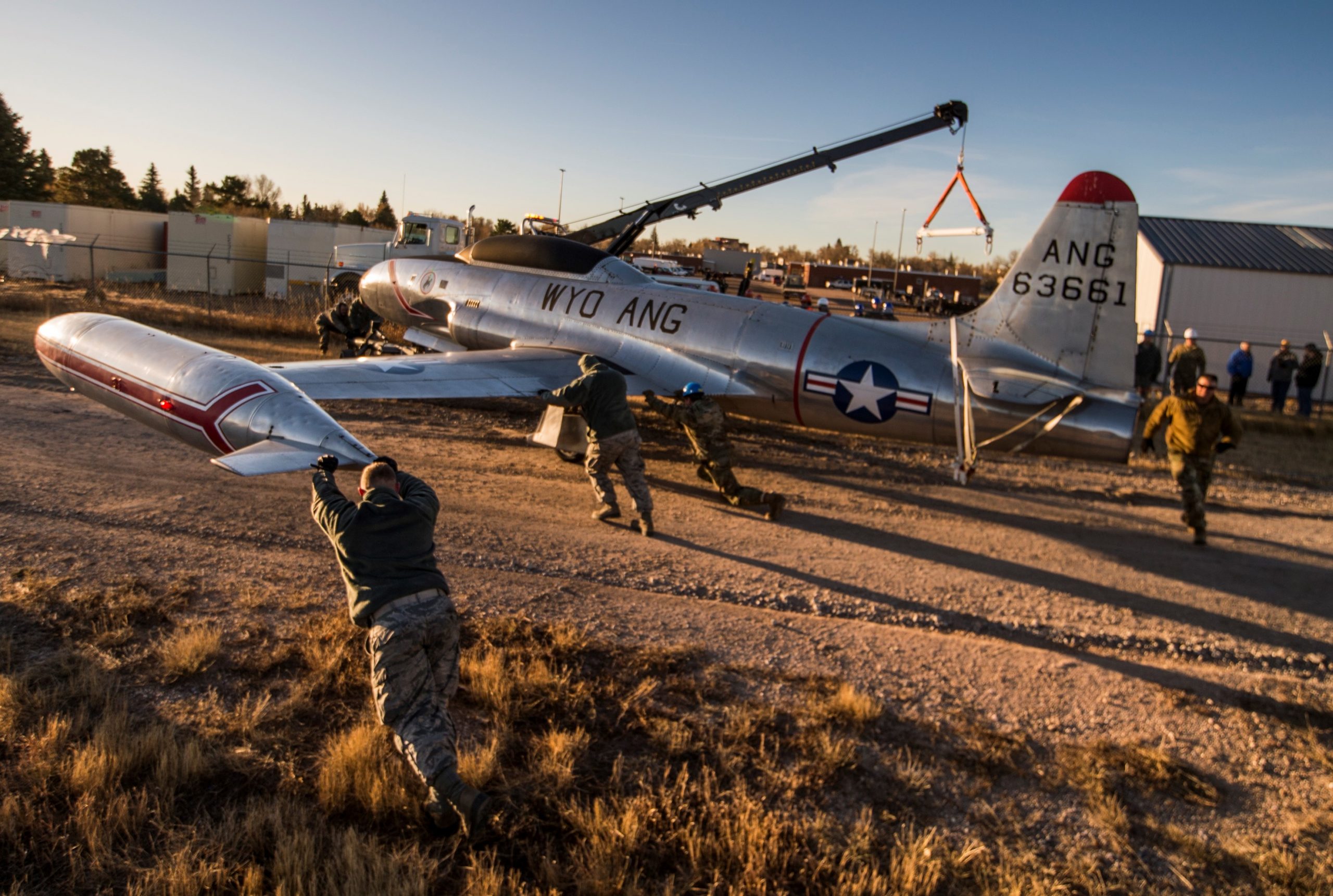
While taking part in Red Flag aerial wargames in February 2017, over Nevada, the RAF Airseeker developed main-landing gear problems and diverted to Offutt AFB in Nebraska.

12FEB2017, Airseeker undergoing landing gear inspection, Offutt AFB. USAF photo by Delanie Stafford.
It was determined that the Airseeker had a faulty main-landing gear sequence valve, which was preventing the gear from locking in the retracted position.
 RAF Airseeker, Red Flag wargames, Nevada, 2017. Photo by Sergeant Neil Bryden.

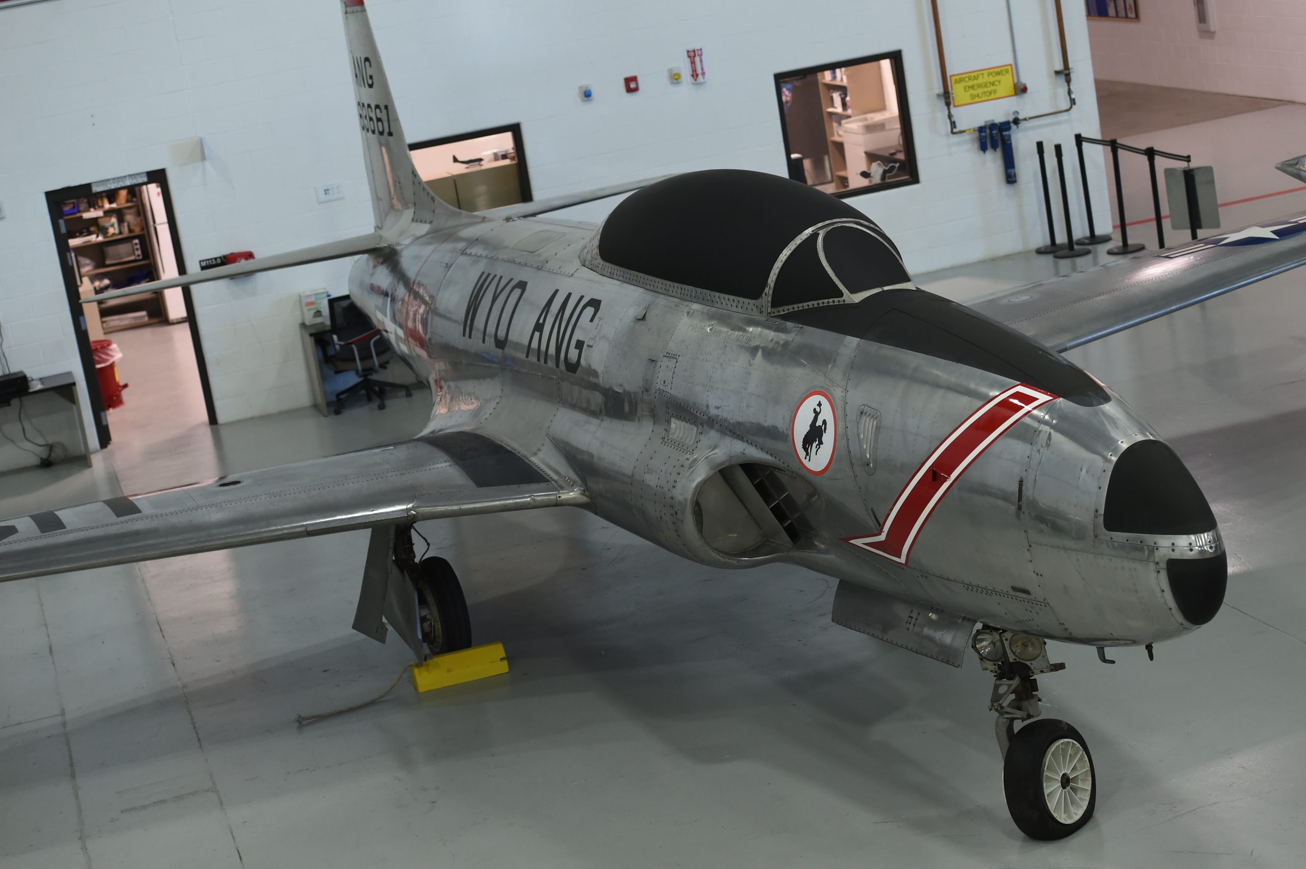
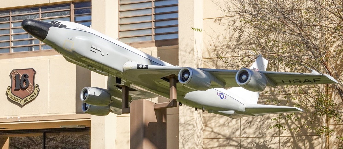
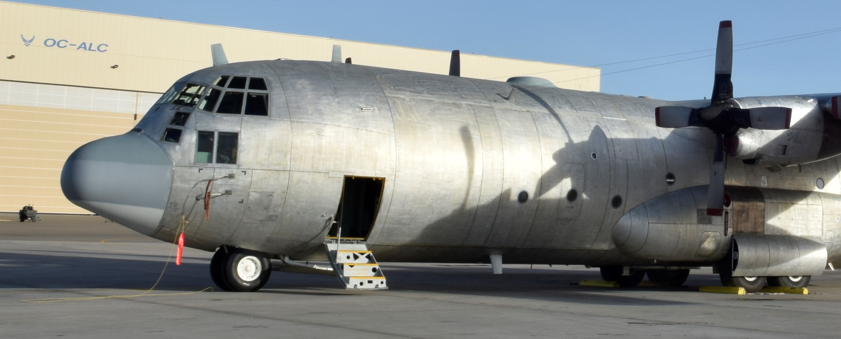
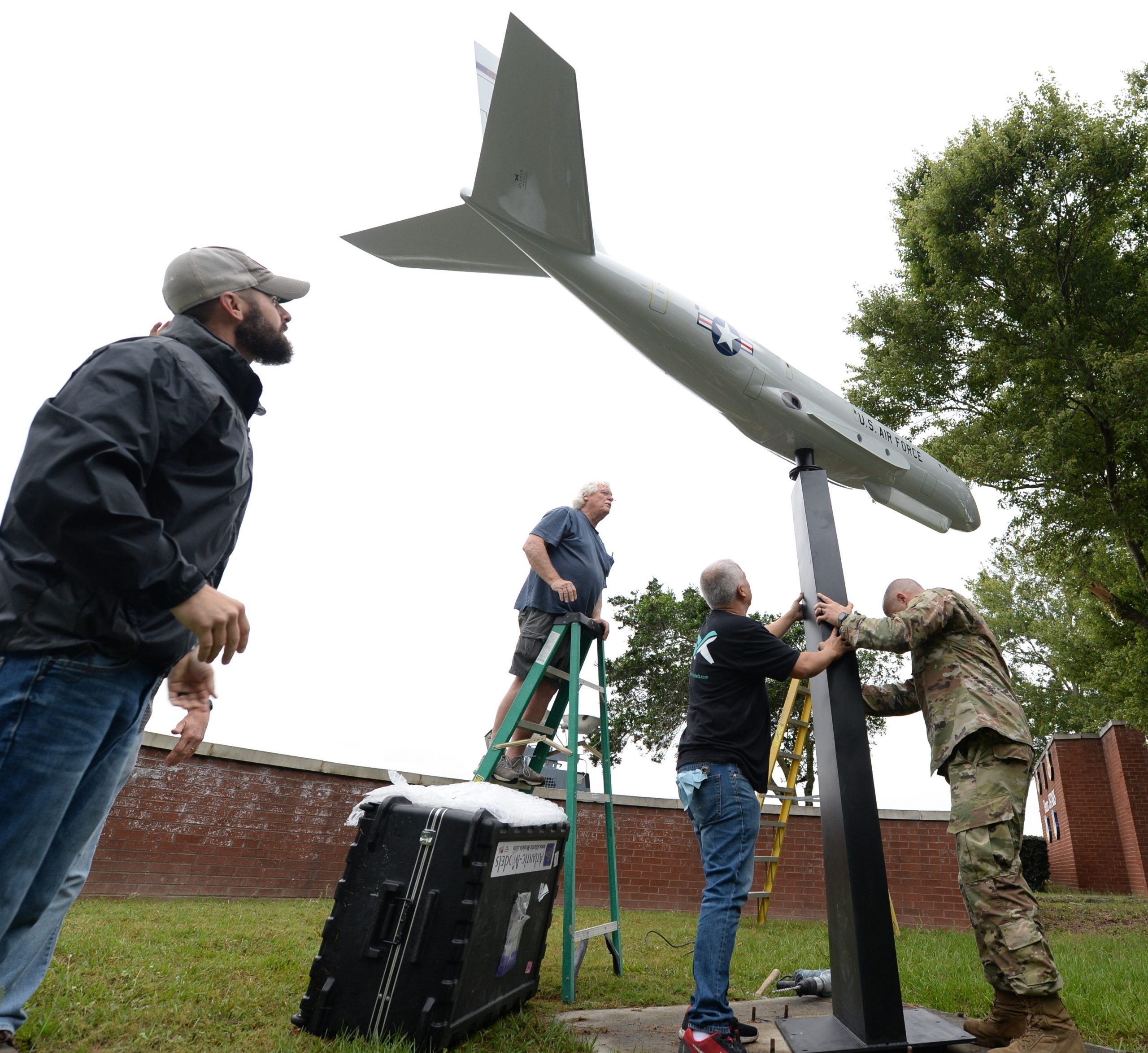
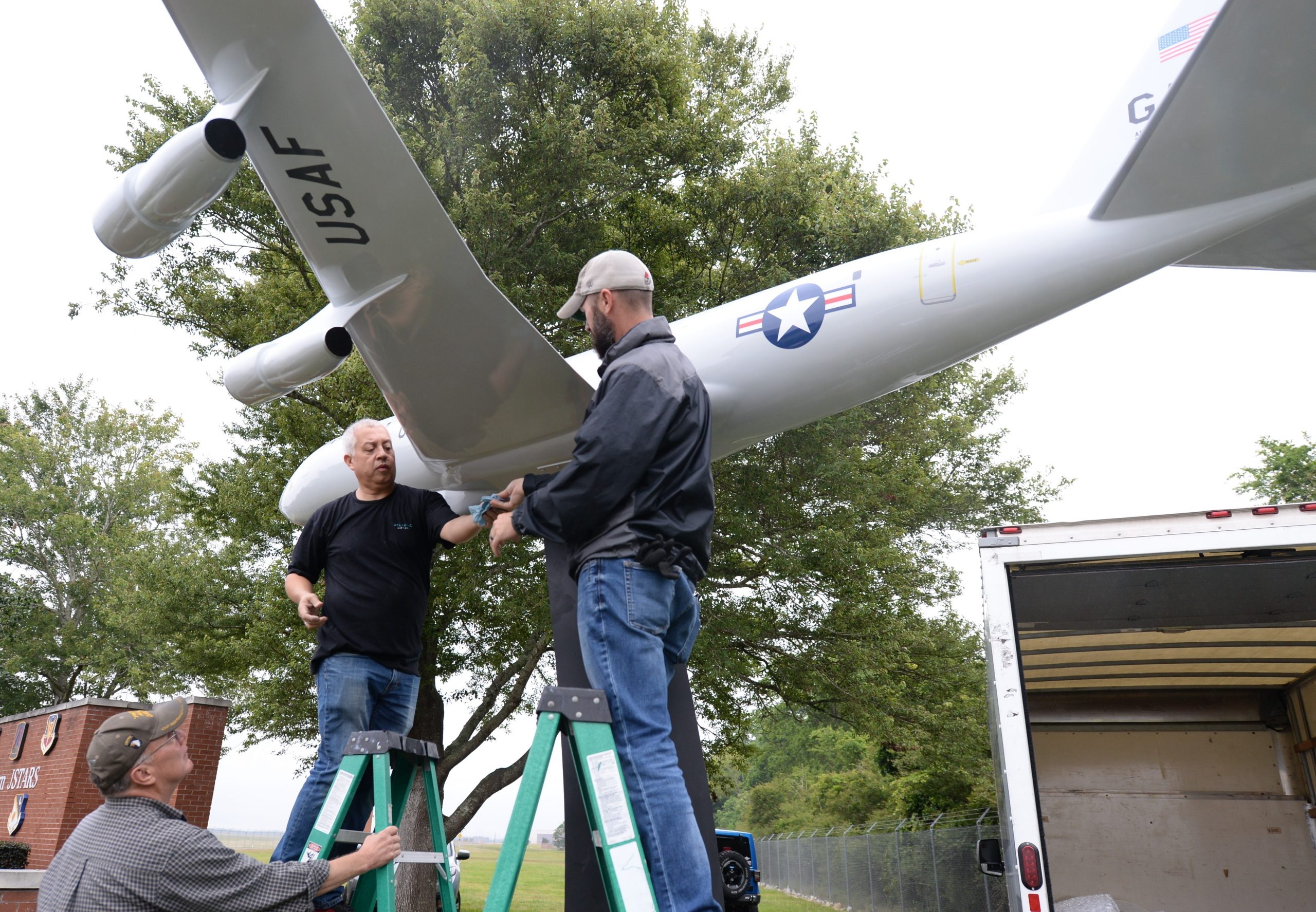
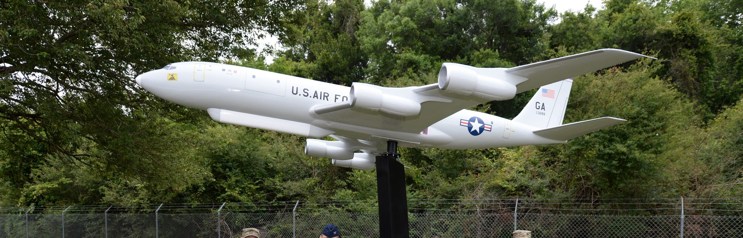
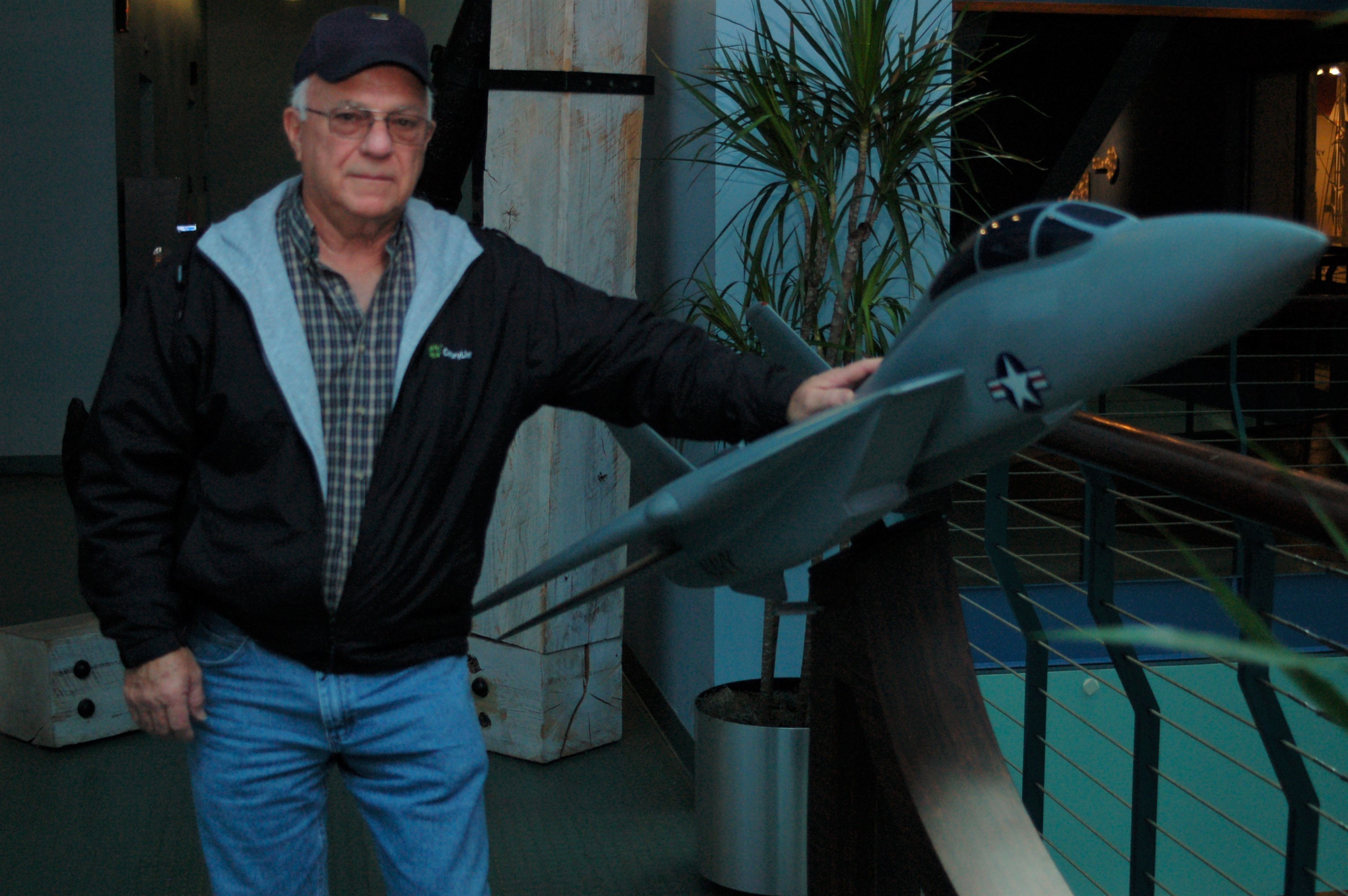
Giant model of an RC-135, Lackland AFB, Texas. Photo by by Nadine Wiley De Moura.
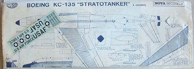 The ancient Nova vacformed 1:72 scale KC-135 came with optional parts which you could use to make an RC version (but it has the older engines since it came out before the CFM-56 version, you could kit-bash using a newer CFM equipped AMT-ERTL KC-135R kit, which was also issued under the Airfix/Heller brands).
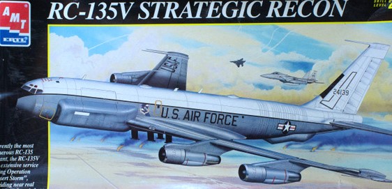
In the 1990s AMT-ERTL issued a 1:72 scale RC-135V, the version used during Desert Storm. Some kit bashers used the kit to model a RC-135W Airseeker.
An old photo of an RC-135, by Forrest Durham.
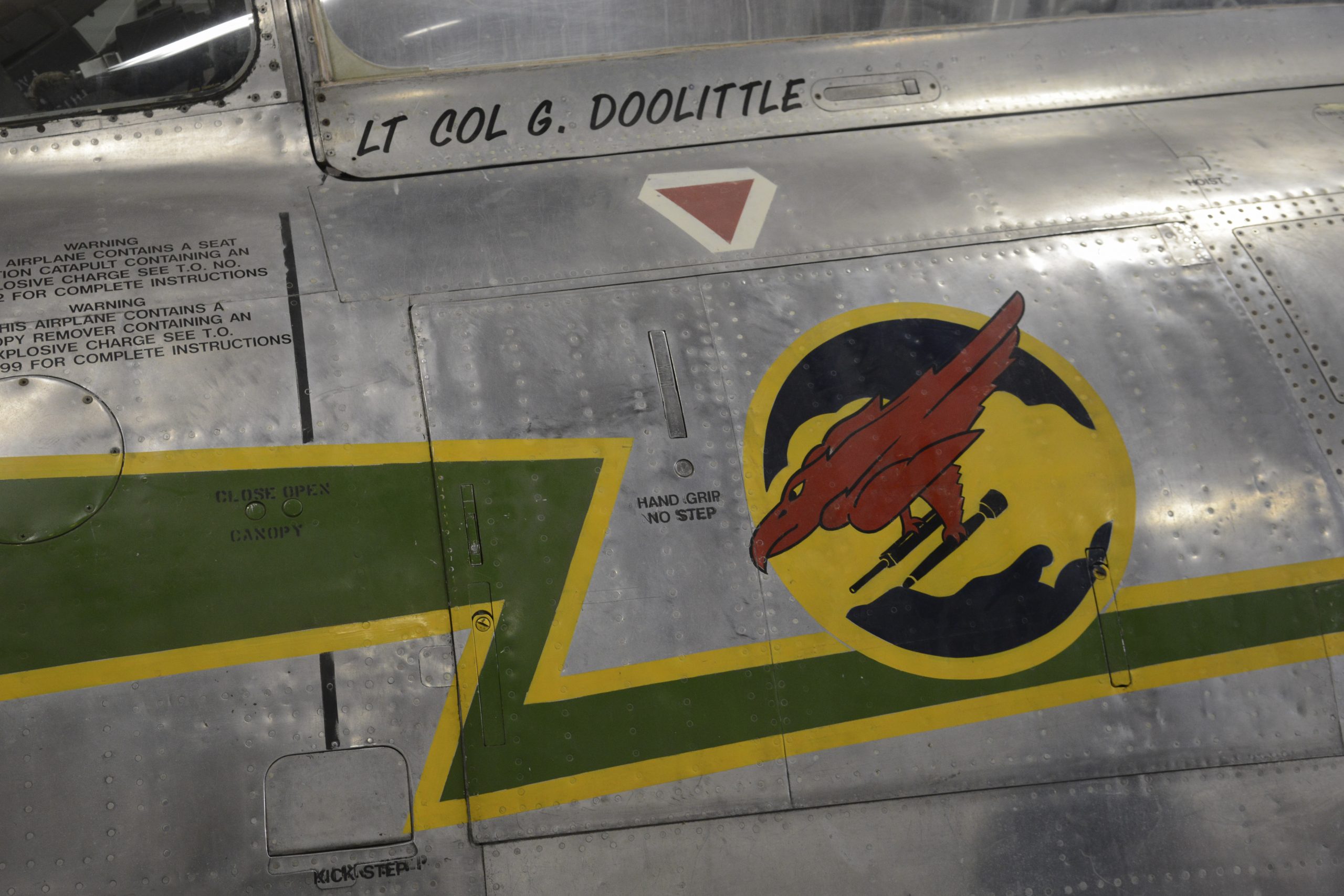
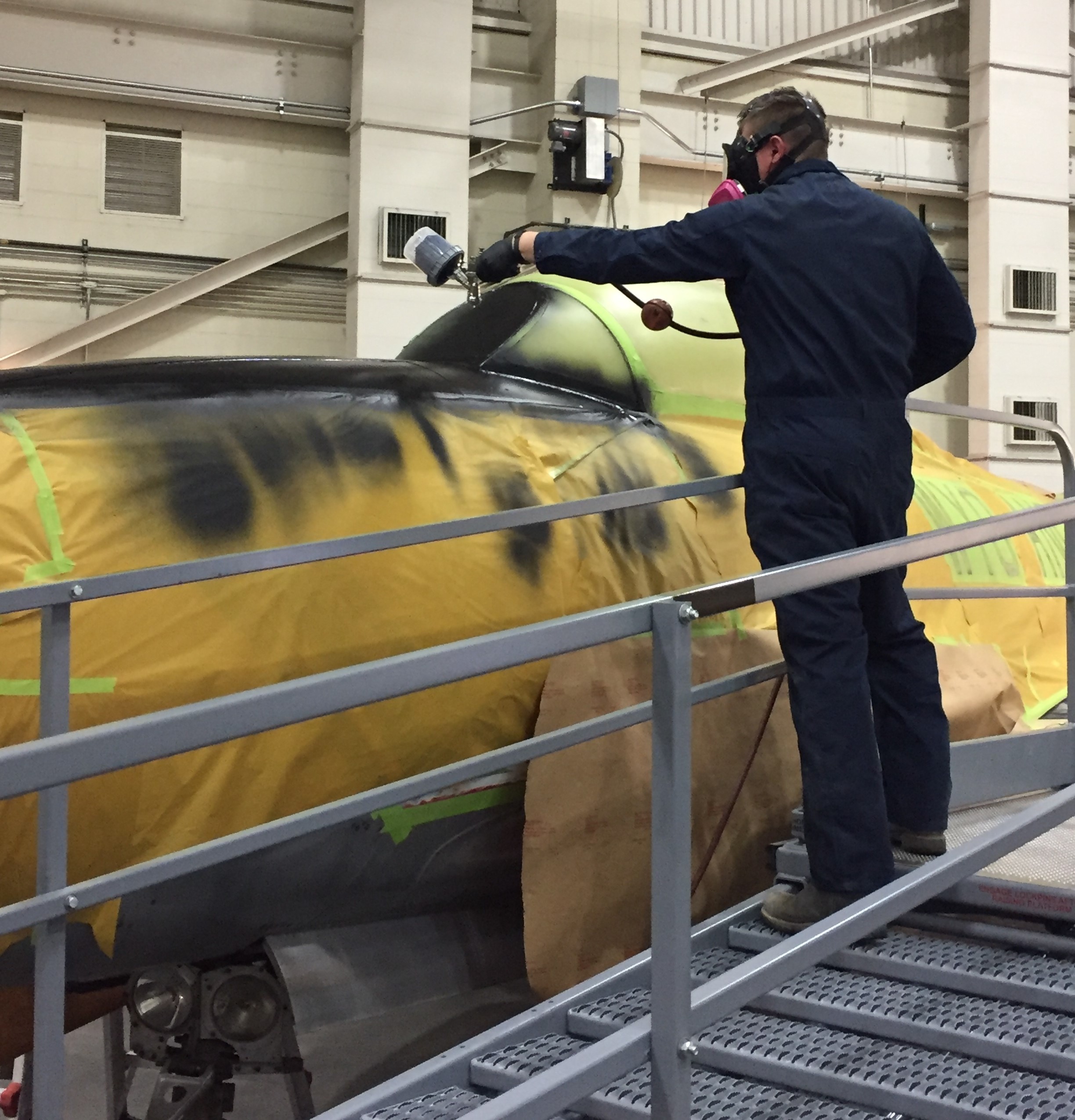
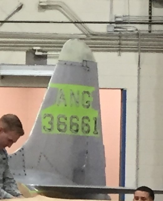
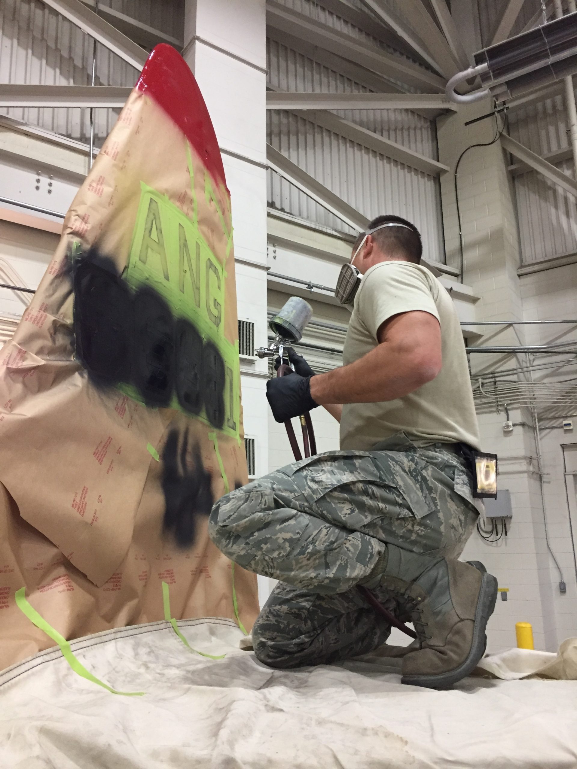
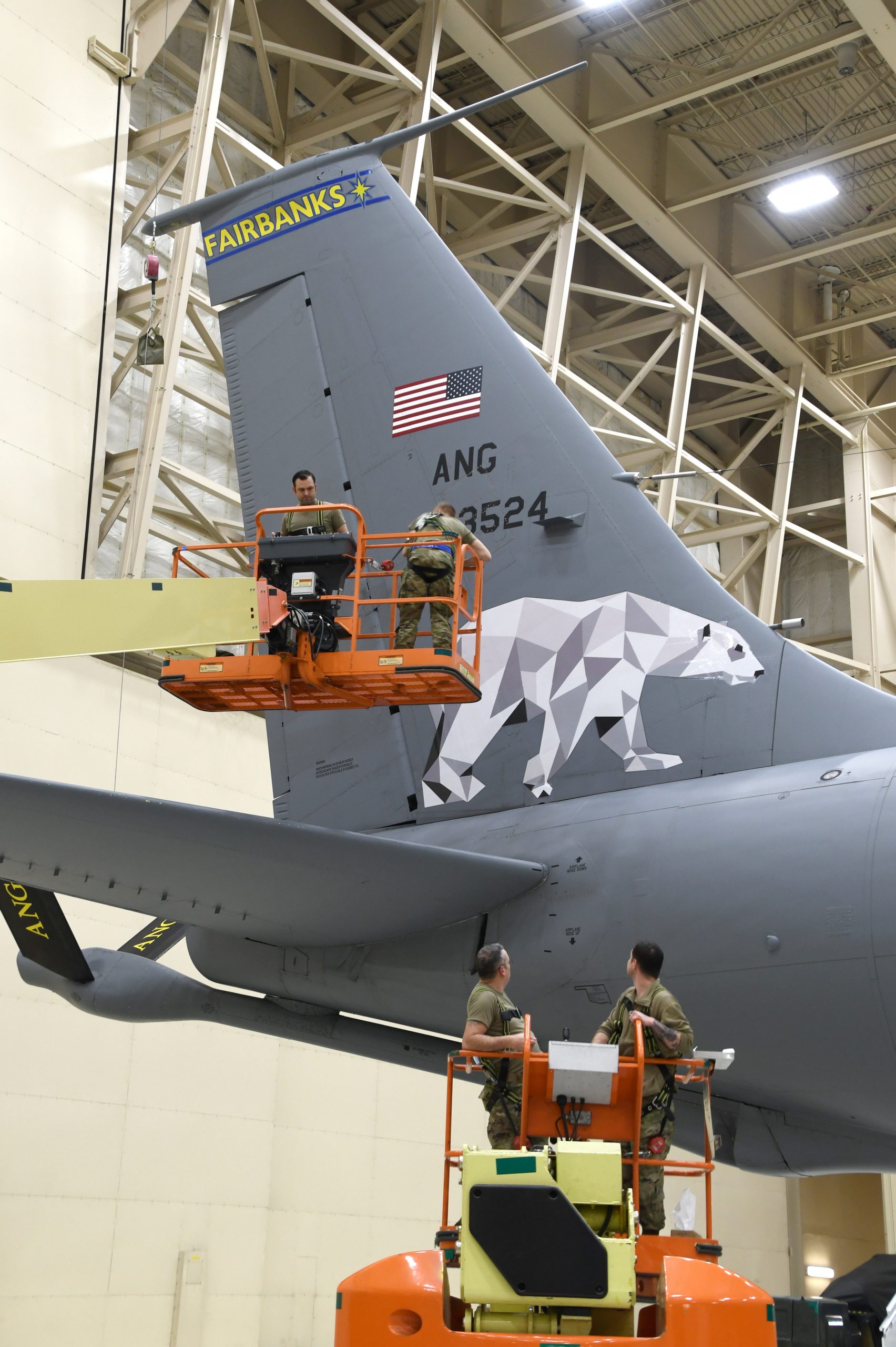
If you are a model builder, pay attention to the year of operation of the RC-135V/W you want to depict, because various antennae bumps and blades will appear and disappear depending on the latest electronic mission configuration. It seems the older the plane gets the more skin growths it develops.

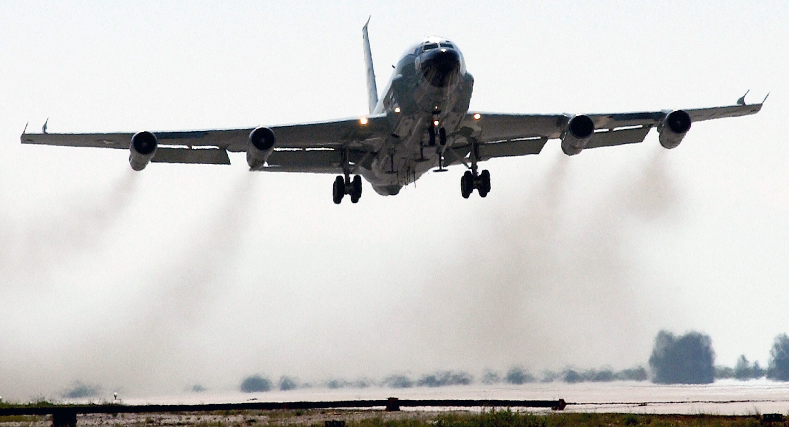
Somewhere in The middle East (South West Asia), 04MAR2010. USAF photo by Technical Sergeant Michelle Larche.

Refueling during the invasion of Iraq. USAF photo by Master Sergeant Dave Ahlschwede, 09APR2003.
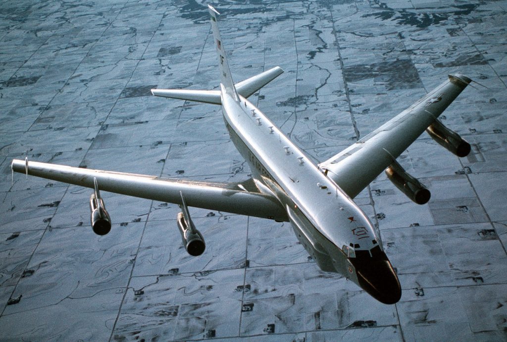
Over Nebraska, 01MAY2000. USAF photo by Master Sergeant Dave Nolan.
01MAY2000, USAF photo by Master Sergeant Dave Nolan.
Don’t forget the bottom.
Departing from a forward operating base during the invasion of Iraq. USAF photo by Technical Sergeant Robert J. Horstman, 28APR2003.
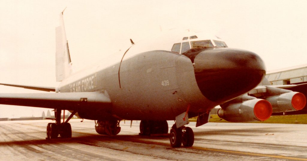
11DEC1991, USAF photo by Technical Sergeant Scott P. Stewart.
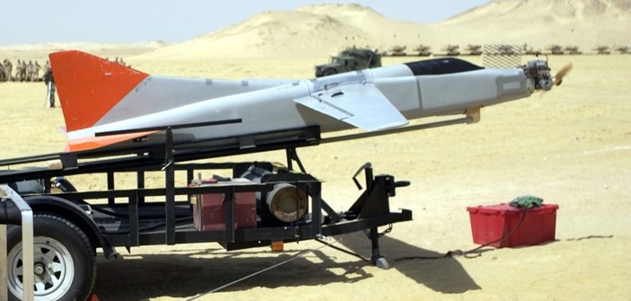
Don’t confuse with the RC-135S Cobra Ball:
Not all RC-135S are covered in bumps and antennae. USAF photo by Senior Airman Amy Younger, 23MAY2020.
Variations of bumps and windows on RC-135S. Notice that the upper part of starboard wing, as well as nacelles, on some Cobra Balls are painted matt-black. USAF photo by Senior Airman Jeremy Smith, September 2001.
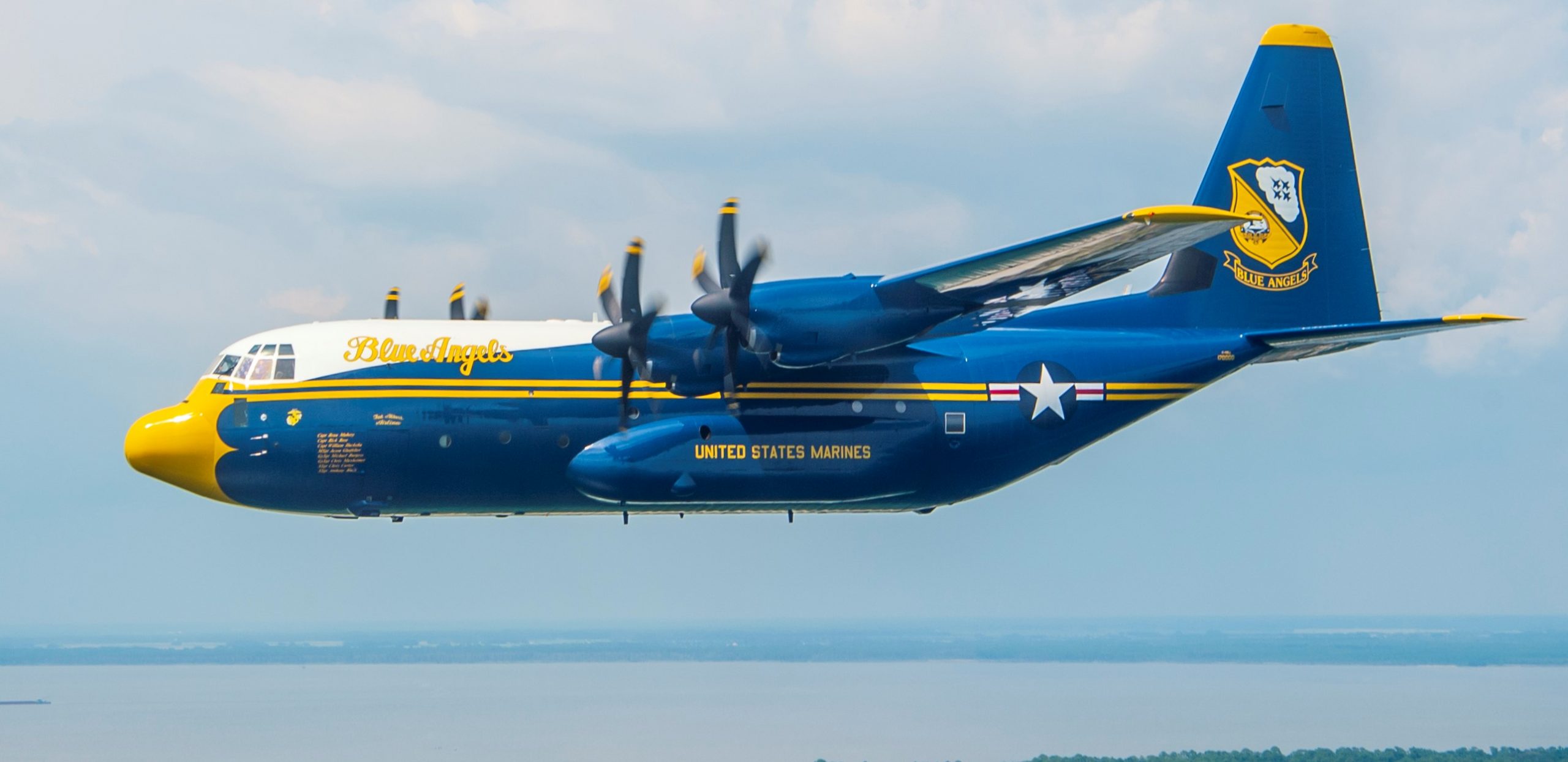
C-130: ONCE A RED COAT, NOW A BLUE ANGEL
Pandemic Overflight: KC-135
EC-135E FIRE-BIRD: 10329 COMES BACK TO LIFE, AGAIN! OR, WHAT TO DO WITH YOUR EXTRA KC-135 KIT.
Vehicle I-D: MLRS, BRITISH RED COATS INVADE U.S. ARMY BASE IN GERMANY!
2018: M777 artillery proof the Red Coats have returned!
2017: U.S. ARMY COMMANDED BY RED COATS?
Canadian Red Coats control U.S. NORAD: SHHH, DON’T “CROSSTELL”, BUT U.S. AIR MILITIA UNITS & CANADA PREPPING FOR TFR EMERGENCY!


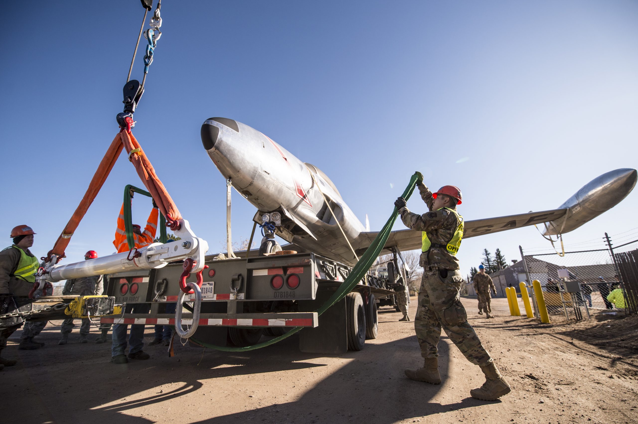
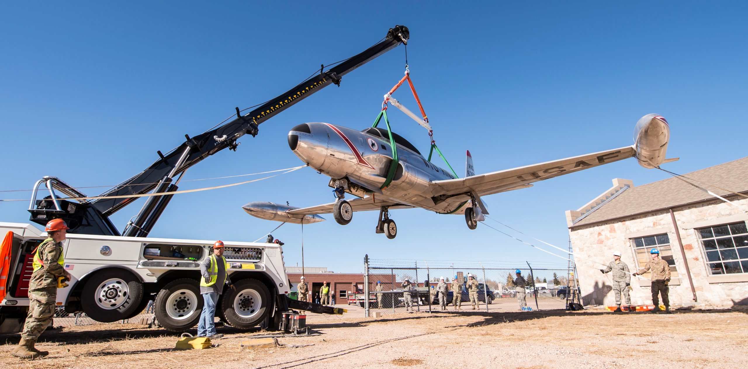
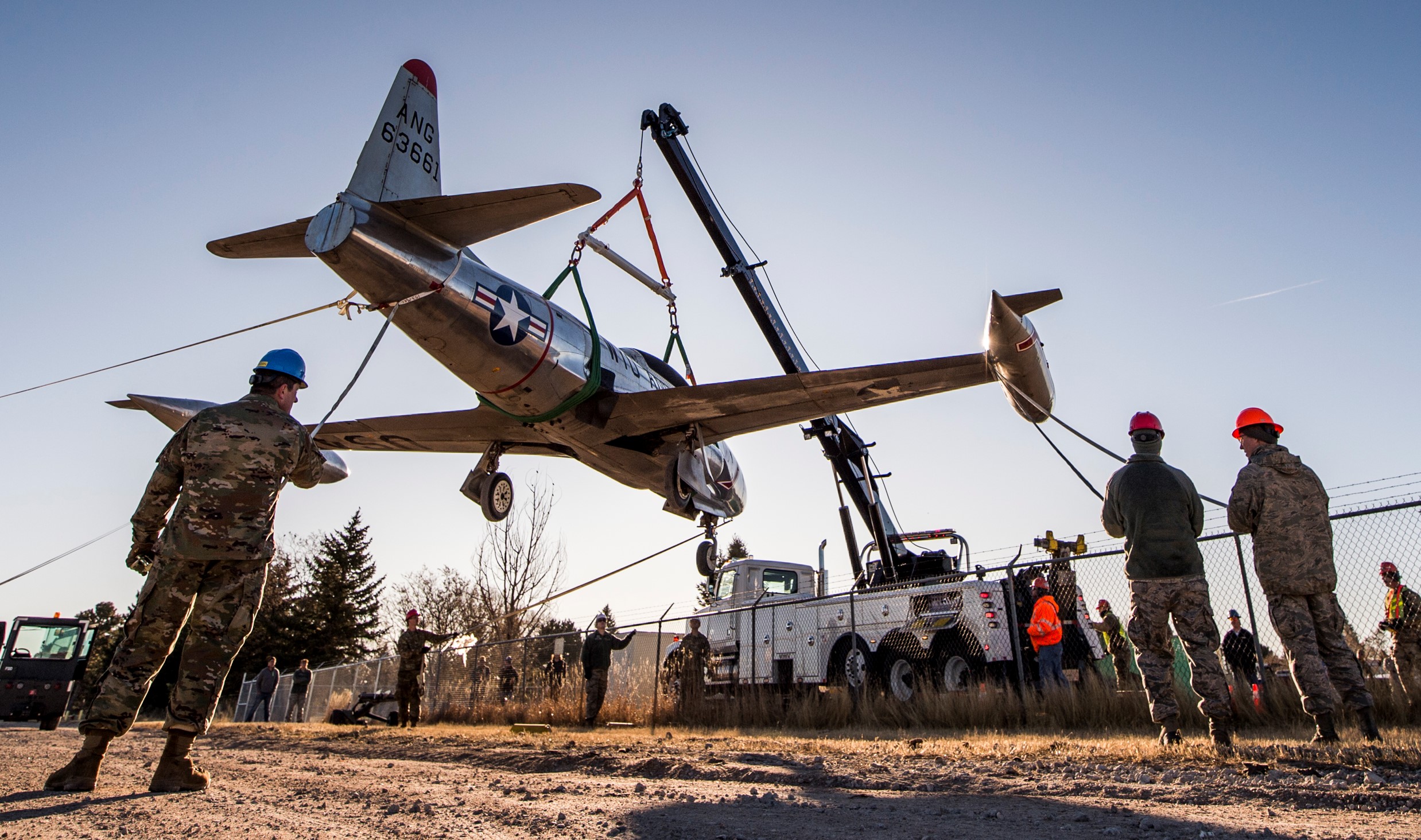
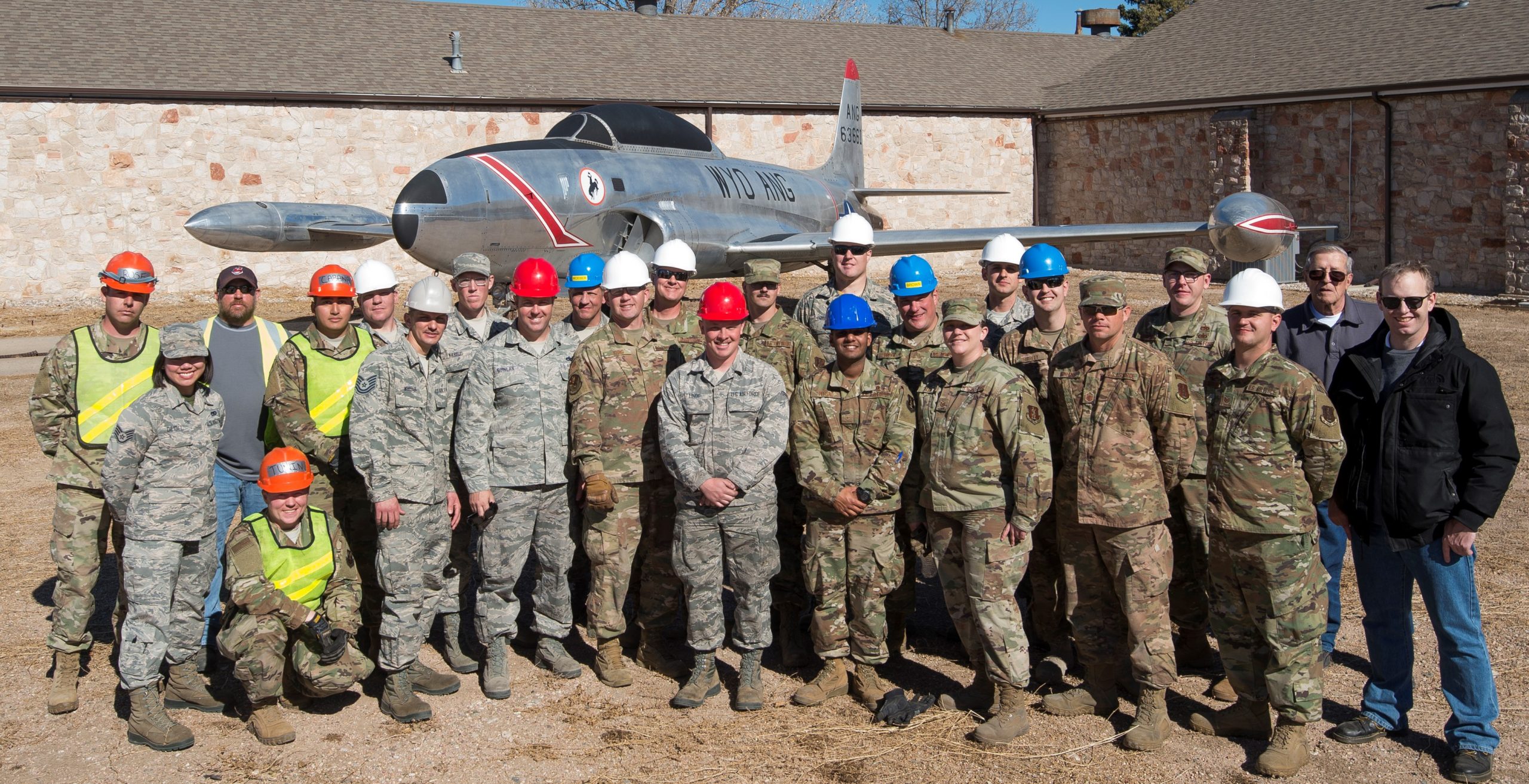
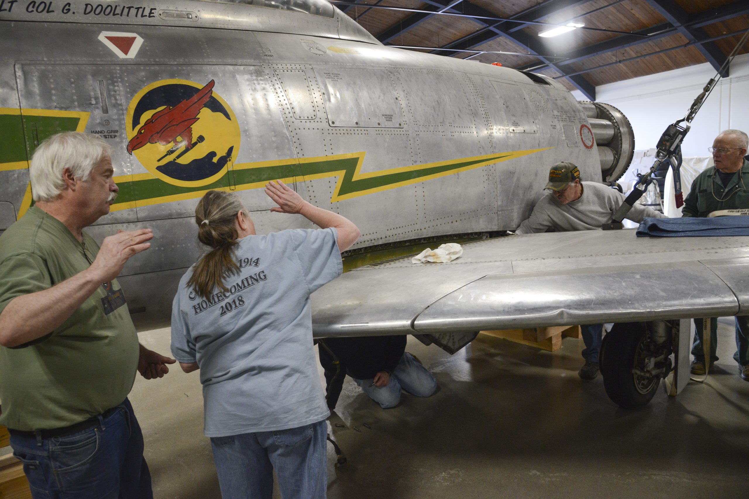
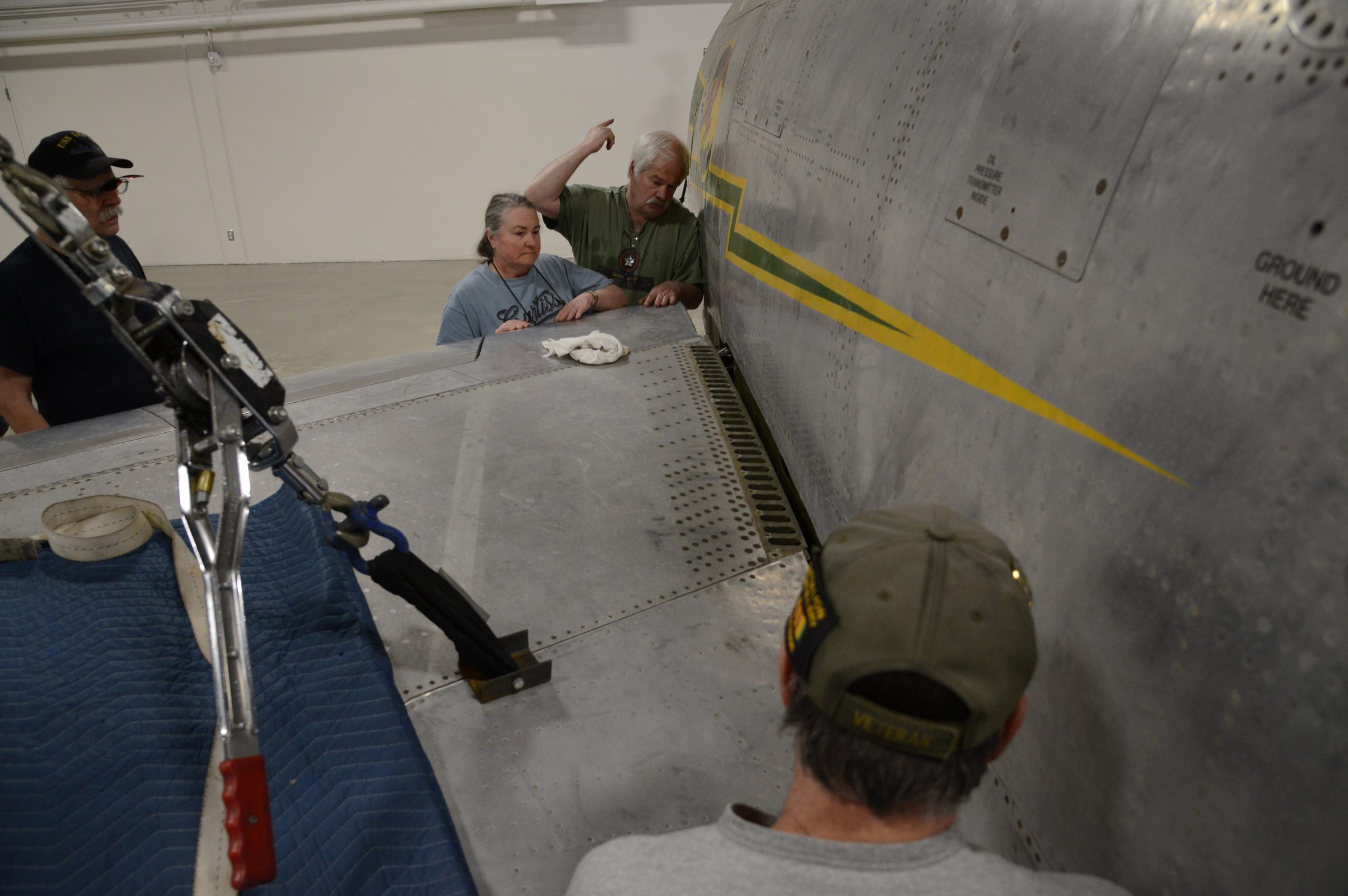
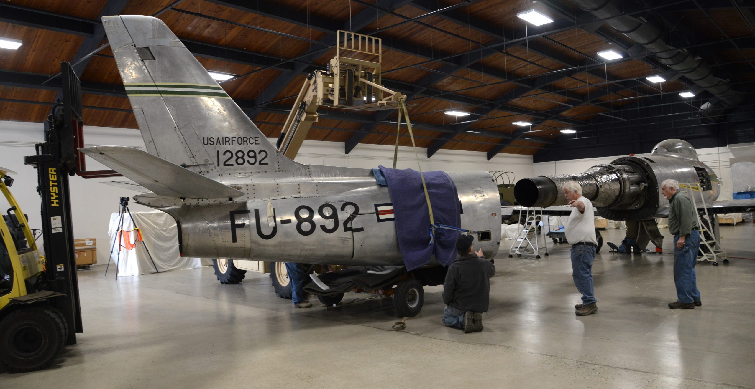
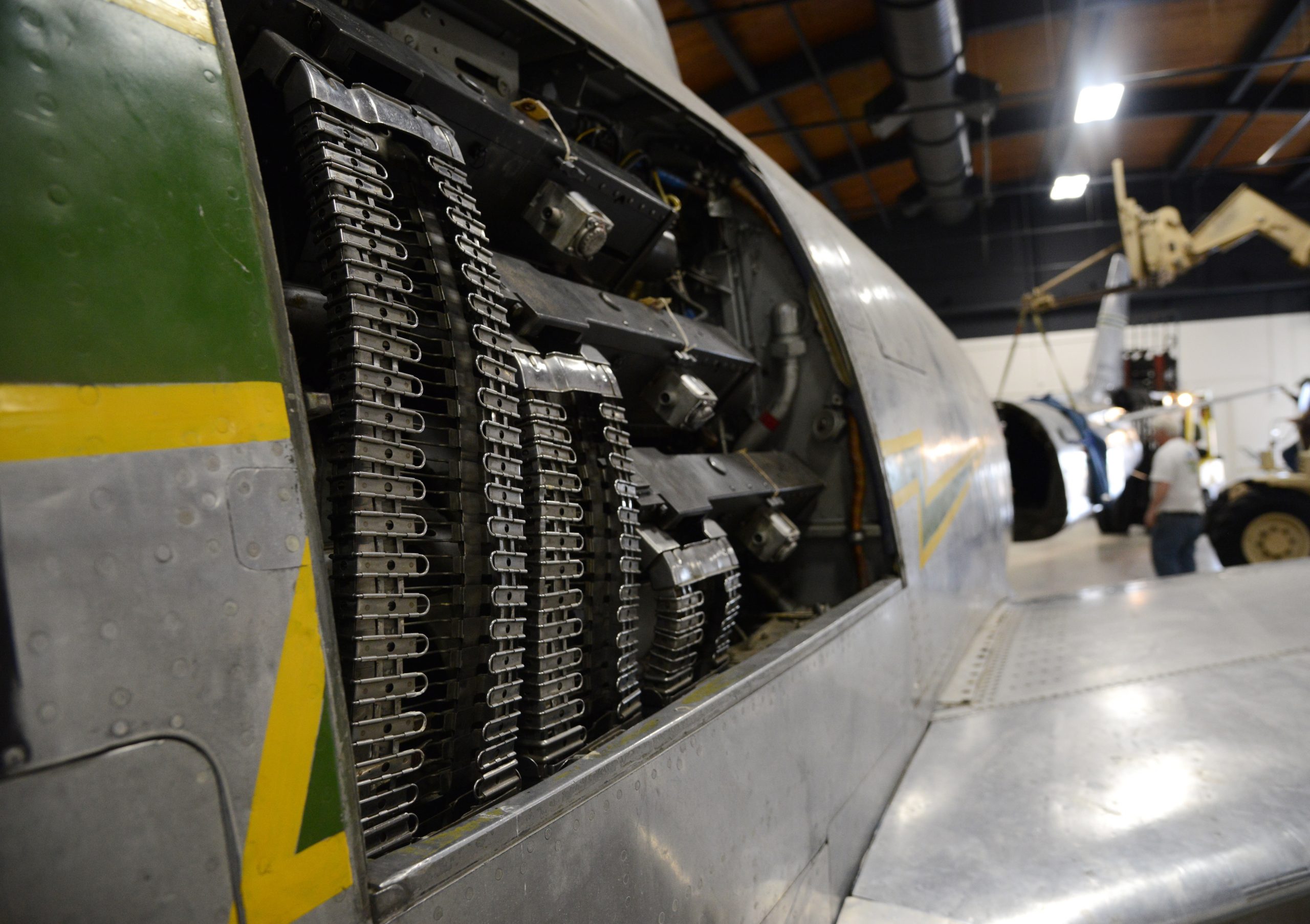
 RF-84F THUNDERFLASH & YRF-84F


 However a reduced scale model of the Full Scale Wind Tunnel was also built: “The excellent energy ratio obtained in the new wind tunnel of the California Institute of Technology suggests that before proceeding with our full scale tunnel design, we ought to investigate the effect on energy ratio of such factors as: 1. Small included angle for the exit cone; 2. Carefully designed return passages of circular section as far as possible, without sudden changes in cross sections; 3. Tightness of walls. It is believed that much useful information can be obtained by building a model of about 1/16 scale, that is, having a closed throat of 2 ft. by 4 ft. The outside dimensions would be about 12 ft. by 25 ft. in plan and the height 4 ft. Two propellers will be required about 28 in. in diameter, each to be driven by direct current motor at a maximum speed of 4500 R.P.M. Provision can be made for altering the length of certain portions, particularly the exit cone, and possibly for the application of boundary layer control in order to effect satisfactory air flow. This model can be constructed in a comparatively short time, using 2 by 4 framing with matched sheathing inside, and where circular sections are desired they can be obtained by nailing sheet metal to wooden ribs, which can be cut on the band saw. It is estimated that three months will be required for the construction and testing of such a model and that the cost will be approximately three thousand dollars, one thousand dollars of which will be for the motors. No suitable location appears to exist in any of our present buildings, and it may be necessary to build it outside and cover it with a roof.”-Elton W. Miller, 26JUN1929


 MX-334 flying wing glider, 1943.
 Bell XP-77 1:1 scale model, 1943.
 Mercury space capsule, January 1959.
 Testing the proposed parawing landing system for space capsules.

 Testing one of the proposed Lunar Excursion Module (LEM) models.


 In 1999, NASA (National Aeronautics Space Administration) decided to test a 1:1 scale model of the Wright Flyer, for aerodynamic data. However, the full-scale Wright Flyer was built stronger than the original for fear it wouldn’t hold up in the wind tunnel (it was tested at only 30mph/48kmh).